Friday, February 7, 2014

Updating my JAMMA test rig


Many years back, I hooked up a spare JAMMA harness to an old PC power supply, a monitor and some repurposed joystick pads.  (JAMMA is a standard connector size and pinout to hook up arcade game boards into arcade cabinets.  Most of my arcade game boards are either natively Jamma (Mortal Kombat, Klax, Block-out) or I have adapters to hook them up using JAMMA.  (Dig-Dug, Pac-Man, etc)).  One board that I've been using with it recently is a knockoff Ms. Pac-Man board, seen in these photos.


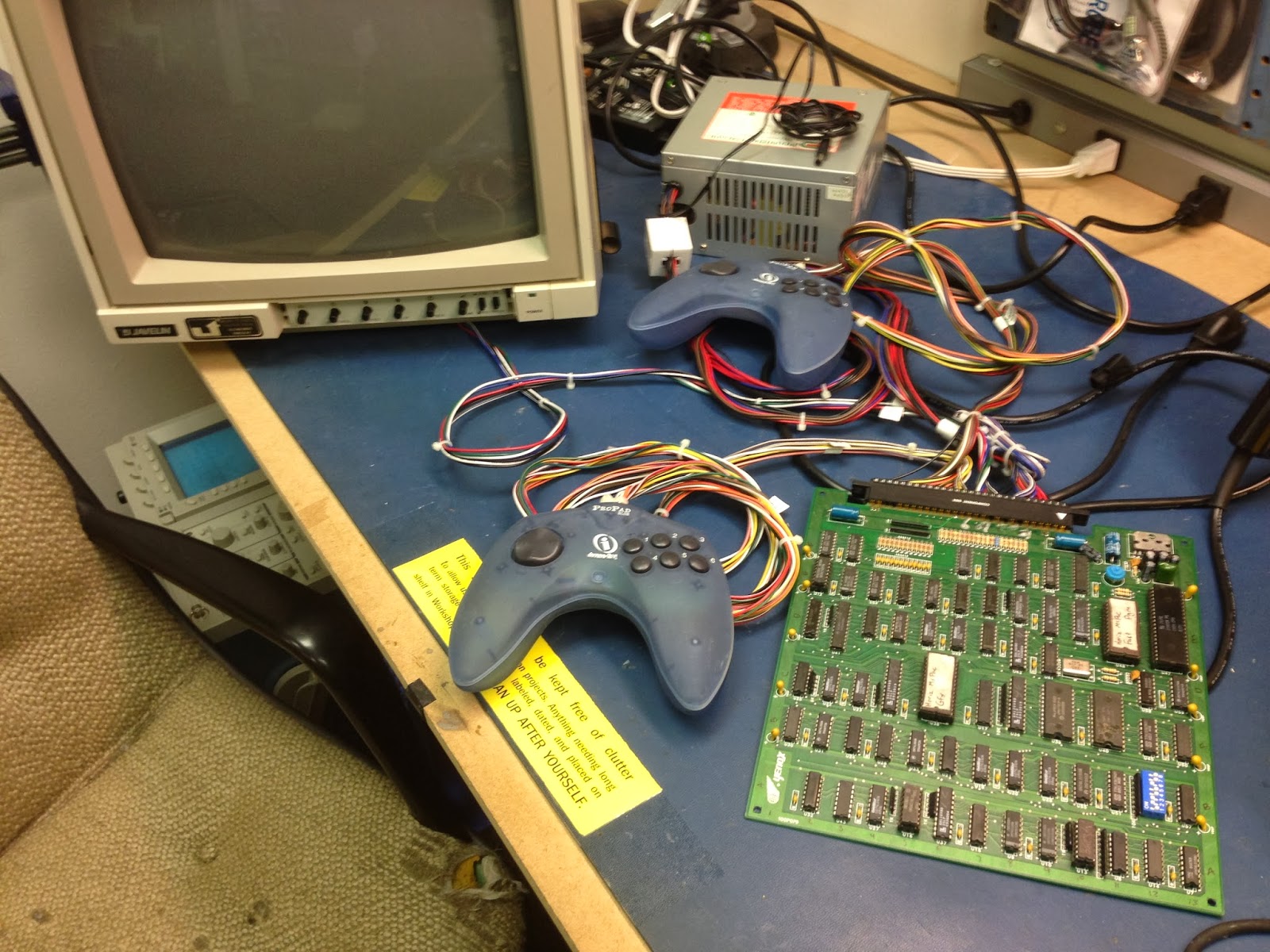
The harness/rig I have was always kind of a hack.  The video and audio wires terminated in a small box with some knobs which were meant to attenuate the signal but never really worked right.  The power switch was on this cord that came out and was weirdly fastened to the side of the power supply.  I decided to clean this up while at Interlock for open night.


It turns out that I happened to have the right 6 pin DIN connector for this old RGB monitor (basically a Commodore Amiga 1084 clone).   So I wired up Red, Green, Blue, and Ground directly to the correct pins on it.  JAMMA spits out composite video, but this monitor takes in Horizontal and Vertical sync.  I knew that some monitors would take in composite sync on their Vertical Sync line, so I tried that... and it worked! Huzzah.

The only video issue now is that the game boards put out video that's slightly too hot/too high a voltage, so I should put attenuation resistors inside the din connector or something...

Even though the JAMMA interface spits out amplified audio, I decided to hook up an RCA plug on the audio lines anyway, to plug it into the line-level in on the monitor.  As long as I'm careful it will be fine.


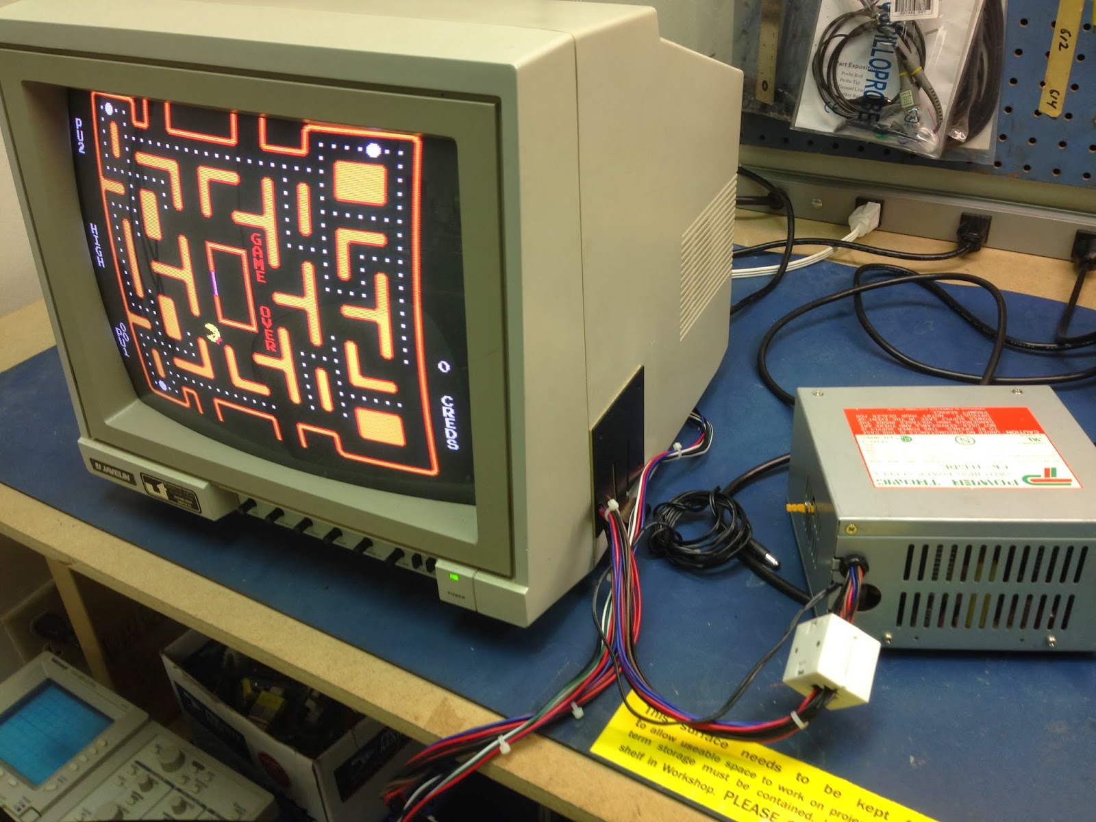
And here it is being driven by my Yenox Ms Pac-Man board with the "Horizontal Ms Pac" rom hack.You can see the power switch sticking out of the side of the power supply there.  It's not the most optimal thing ever, but it's substantially cleaner than before.  Perhaps I'll replace that switch with a nice carling switch in the future.  I'll need this test rig for the next task, which is fixing the audio on this board.  It sounds horrid...

This was originally posted on the Interlock blog on January 30th, 2014.

Tuesday, February 4, 2014

Repairing the audio on a Pac-Man arcade board.

I got this knockoff JAMMA Ms Pac-Man arcade board many years back.  It's got two ROMs instead of the authentic board's 6 (9 for Ms Pac), and is substantially smaller than the "real thing".  The only issue is that the audio is poor... REALLY poor.  It makes sounds but they're... wrong and noisy.


I took over some desk space at Interlock and got to work.  (I should note that the beverages you can see here are other people's, not mine. ;)

I traced the audio circuit on a real Pac-Man schematic (seen on my laptop's monitor), and buzzed it out on the Yenox board to try to corrolate the two.

I had to trace four similar paths from a quad flip-flop, through a quad bidirecional switch, to the audio output.  It got really confusing at times, and took me probably a bit longer than it should have.  For the most part, they were pin-for-pin correct as far as how they were wired.  These chips have the same device (eg, a flip flop, or a logic gate) repeated 4 or 6 times.  In some cases here, the Yenox board had a different one of these devices hooked up, which added to the confusion.

This portion of the circuit uses 8 resistors to make a digital-to-analog converter. These generally work by having different resistance levels, usually something like multiples of eachother, eg,  10k ohm, 22k ohm, 47k ohm then 100kohm.  I traced out all of the lines on the Yenox board and I found out that not only were the resistors in the wrong order on the board, but they were also wildly wrong (47 ohm instead of 4.7k ohm), which you can see in this table I made:


You can see these resistors here on the Yenox board, right next to the JAMMA connector.  They start from the left with R1 (my notation.)  The printing on the board completely matched the resistance values that sat on them, so it's obvious that the engineer who made this board seriously screwed it up in the design stage.


I replaced resistors R3 - R7.  I put them in with the gold band closer to the JAMMA connector, rather than the other way around.

And now it sounds near-perfect.  There's a little bit of popping left, but I was getting tired and decided to head home for the night.  I'll hook it up to an oscilloscope at some point and see if i can figure out which line is causing problems.

For what it's worth, I also did the same as this on the video path DAC, seen in the above picture as the next three groups of resistors.  In the above, the group of four and then the group of five are for audio, then the next group of three is for the "red", next three for "green", next two for "blue", and the remaining two are for the sync.  Again, there were some 47 ohm resistors mixed in, and notice two of the three in the "green" section are identical (red-red-brown)... which is surely wrong.  Color is now perfect on the board too!

This post originally appeared on the Interlock project blog 2/2014.