Thursday, November 15, 2012

EPROMs part 2: Success!

NOTE: This article was originally posted over at the Interlock blog.

This is a continuation of a previous article.  Quick summary: I tried to build a device for dumping an EPROM via Arduino, and I constructed a device that had no chance of working.  Oops.

This post will continue where that one left off.  I'll walk through some of the process to hopefully get to a solution that works...


To summarize the overall project;  I want to build a device that will illuminate an UV light-erasable ROM (EPROM) device, and also dump out its contents. I will then take the contents, display them as a graphic, and animate them over time as the bits fade away into an erased oblivion.


When we last left this, the above circuit was what I was going to work with.  The Arduino would shift out a 16 bit address, which will be stored in the 74HC595 serial-in, parallel-out shift registers.  Those would output to the address lines of the EPROM device. The 8 data line outputs of the EPROM then are read in directly by the Arduino.  I started to look around for the parts, and I was planning to buy them from Sparkfun.com, for a very reasonable price.  I was all set to place the order, but then I started thinking about other ways to sample the data, and then it hit me...

In the late 1980s, I had an Amiga 1000 computer (see previous post about restoring it).  We used Macintosh SE computers in High School, and as a result, we bought the "AMAX" Macintosh emulation system for the Amiga.  It was a lot easier to carry a floppy or two, rather than a SE or SE/30 in a plastic milk crate, not to mention that MacWrite was a substantially better word processor than TextCraft. ;)

AMAX consisted of software you run that emulated the Mac's hardware, as well as a "cartridge" that plugged into the floppy drive port of the Amiga.  I remember hearing that they went with the floppy drive port because it was the only appropriate port identical on all Amigas that were available at the time. (Amiga 1000, 500, 2000).

The cartridge served two functions. First, it let you plug in a Mac floppy drive right into the Amiga so that you could read and write 800k Mac floppies directly.  There was something about Amiga drives and Mac drives supporting a different number of drive speeds, so full Mac compatibility on the Amiga's drives was directly impossible.  Future versions of AMAX that used an internal card on the Amiga 2000 worked around this issue.  It was possible to make a floppy that supported just the sectors/speeds that were the same on both, but they only stored 272k of content.  But I digress...

The other function of the cartridge was that you needed to plug in Mac roms into it, which the software would read in as it starts.  Rather than storing the ROM on the Amiga, this protected the copyrights or whatever.  But the important thing here is the function.  I had picked up a few AMAX cartridges for $2 apiece at the awesome Active Surplus on Queen Street in Toronto a bunch of years back, so I dug one out.

Left-to-Right, you see: Amiga D23 floppy connector, for connecting it to your Amiga, two 28 pin rom sockets, two 74LS393s, one 74LS165, a resistor, some diodes, a 74LS139, the Mac D19 floppy connector on the bottom, then the Amiga D23 floppy connector for adding additional Amiga floppy drives.

I've started to trace out the circuit, but it became obvious quickly that it was optimized for board layout rather than what I would consider to be a sane arrangements of data lines.  For example the 8 data output lines of the ROMs go into the 74LS165 PISO shift register out of order, so they need to be reshuffled once captured in the host computer.

Instead I decided to desolder the chips!  My guess at the original function is something like: the Amiga issues a clear to the 74LS393 binary counter chips, ganged together to yeield a 16 bit output, rather than two dual-4 bit outputs.  This will reset their 16 bit output value to 0.  The 74LS165 parallel-in, serial-out register then latches the 8 bit output from the ROM, and provides it through shifting to the Amiga via the floppy port.  From there, you need to simply pulse the clock on the '393, and it will increment through every address. Then you just latch and shift in the data. There's also a 74LS139 demultiplexer, which might be responsible for sequencing through those events, or perhaps something to do with the Mac floppy drive. I had a slight mishap and lost the 74LS165, which is okay since I didn't need it for this project anyway.  Regardless, $2 plus some time -- I'm already ahead and I haven't even removed the D23s yet (which are the same size as Amiga RGB Video connectors! Perfect for another project...)

For fun, here's the board with no components on it.


With a slight change in gears I can adapt my design to use the parts I now have in my toolbox thanks to my desoldering tools.  Instead of the Arduino shifting out an address, it will instead do the process described above.  It will first clear the 393s, then alternately cycle between clocking out a pulse to increment their values, and reading in the value directly. Since I'm accessing the ROM data from start to finish, sequentially anyway, this solution works out perfectly.  I also show four LEDs in the above diagram. Three for various status, one for UV illumination.

Here is a close up of a 27C128 part. This one has Pac-Man programmed onto it... of course.  You can see through the quartz window, and down onto the EPROM silicon itself.

Here we see the pins on the Arduino, and how they connect to the shield's bus connections, along with the LEDs.  I could draw this up in a computerey drawing program, but sketching it out in Sharpie on graph paper is just quicker... ;)

Here are the  two 74LS393's.   You can see their connection to the address lines on the ROM, as well as the cascading of the counter, e.g. from 1QD to 2A, and from 2QD to 1A on the second chip.

And the wiring for the 28 pin socket, including the 3 pin (two-way) jumper so that i can use smaller 24 pin parts as well.

About the UV illumination...  The data sheets for the EPROMs show that they should be erased with 253.7 nanometer light, at 15-20 minutes, 2.5cm distance at 15 Watt/seconds per cm^2.  I dont know how to measure this with respect to LEDs, but I'm going to just wing it and see what happens.  The sheet also says that 253.7nm is the optimal wavelength for erasing them, but anything below 400nm should work.  I believe the UV LEDs I have are somewhere between 350nm and 400nm, so it should work.  The other issue is that the LEDs are substantially less powerful, probably a tenth to a hundredth the power. We'll see once we get this going, but I expect it will take on the order of weeks to erase a rom, rather than minutes.

The good thing about this project, in comparison to using EPROMs functionally, is that you want speed of erasure for functional use.  I personally found that my eraser worked on most of the devices I own in about 10 minutes.  I would often have a chip or two in the eraser, while programming and debugging others.  It worked out fairly well.  For this project, it's completely okay if it takes on the order of hours to erase a device.  I'll find out how well it works once I get it going.  I may use more than one LED just to speed it up a little, in case it takes on the order of days instead of minutes or hours.
I started laying out the board at home, wiring in just the LEDs, and figuring out the best layout for the chips.  I used the DIY shield for Arduino from AdaFruit.com as the foundation to build this upon.  I wanted to leave space for possibly using larger chips in the future, so what is the bottom of the board here has space for a few extra data lines if i re-route that red power line.  The '393's are layed out so that the one on the right, which addresses bits A0-A7 has four of its lines directly lined up.  This was to try to make it a little easier to wire up.


I bought some wire wrap wire for address, data, and control lines, and did most of the work of wiring those up one evening at Interlock.  I used red for control (counter clear, clock data cascade lines) as well as eprom address lines.  I used blue for data lines.  In the above pictures you can see how the wires were routed around (there was some more writing on the bottom, obviously.) You can also see how the UV LEDs are mounted with some stiff solid core wire.  I reduced the number of LEDs to two plus the UV LEDs for no real reason at all.  (There is an Arduino underneath there somewhere...)

On the two images above, you can see a jumper on the left of the first image, bottom of the second image... this changes what one pin is used for.  For smaller EPROMs, pin 26 of the 28 pin footprint is used for VCC, powering the chip.  In the larger packages, VCC is moved to pin 28, and pin 26 is used for Address line 13.  It's confusing.  A table that shows all of the pinouts doesn't really help too much, but it was necessary so that I could figure things out for wiring it up.


Next is firmware. I wrote a pretty simple program for the Arduino that simply enables the EPROM, resets the counters, then clocks through the addresses, reads them in and sends that data down through the serial link.  After getting the enable lines wrong (active low, rather than active high), I managed to get it spitting out actual accurate ROM contents.  As you can see in the above, it read out of the ROM (right half) 0xf3, 0x3e, 0x00, and so on.  In a disassembly of Ms PacMan on the left, you can see these bytes in cyan, just to the right of the red numbers 0000, 0001, and so on.

The other half is a simple program that runs on a host computer that simply reads in serial data and logs it out to a file.  That content looks like this:
f33e00ed47c30b23772310fcc9c30e07060708090a0b0c0d0e0f101114f532c038002a804c702c712c20022ec022804c3aaf4e324a503aec4ea73aef4e20033ae187d75f2356ebe9e146234e23e51812 
f33e00ed47c30b23772310fcc9c30e07060708090a0b0c0d0e0f101114f532c038002a804c702c712c20022ec022804c3aaf4e324a503aec4ea73aef4e20033ae187d75f2356ebe9e146234e23e51812
I've now had this running for 12 hours with no change in the bits at all.  I'm thinking that it will require running for upwards of a week or two to have any affect on bits.  I may need to just drop the Arduino and ROM shield into my eraser to get the results I'm looking for... or at least a "control" to prove that the idea has a chance of working from here.

If nothing else, I now have a way to read EPROMS from an Arduino.  Awesome!

Wednesday, November 7, 2012

EPROMs and Failure

One of the things that comes with working on a lot of projects is failure.  Not everything works.  I've had my share of projects that for one reason or another, just didn't work out.  Tonight, I worked on one of these.


For a long time now, I've had some ideas that center around EPROMs.  I've been using EPROMS since I started getting into arcade machine collecting.  EPROMs are programmable devices where you can store bytes of memory in a fairly stable method.  They look like any other microchip, except that they have a transparent window on the top (usually quartz, even though it looks like glass).  If you look in the window, you can see the chip die in there, which I usually think looks like a tiny tennis court.

The above image shows a few different size.  The one on the right is a 2716, 16 kilobit (2 kilobyte) device.  The one in the middle is a 27C256, 256 kilobit (32 kilobyte) device.


To use an EPROM, you place it in an eraser, which is usually a ultraviolet light (often a fluorescent, non-filtered black light tube) with a timer, for about 10-12 minutes or so.  This sets all of the bits in the device to 1's.  (0xff hex).


Then you take the chip, and plug it into a programmer.  A computer tells the programmer what zeroes to write and where, and you end up with a chip that has a program or some data stored in it, so that it can be read out later.  Often, the window is then covered up so that they are not accidentally erased over time from ambient UV light. One data sheet I read said that 1 week in direct sunlight, or 3 years in normal office lighting will erase a device.  The programmer above is my Needham's EMP-10.  It has a 30 pin simm-looking slot on the side with 3 snap-in cards that configure the programmer pins so that it can handle a variety of different target device EPROMs.

This process has fascinated me since I started burning ROMs for use in arcade machines.  This is where this project comes in. I've had a few thoughts about things to explore here...

First of all, it should be possible to determine which bytes are in which physical locations on the device by casting a shadow or projecting an image onto the die from the eraser.  It should be possible to determine this by projecting different patterns on the die with the UV erasing light.  Obviously, it has to be well focused; this has to be quite precise.  A project for another day...

Secondly, I thought a fun project might be to read the pattern produced by erasing the device.  I would program all zeroes to the EPROM.  The chip would be plugged into an Arduino, to read the data out of it.  The Arduino would also control a UV LED or two which would illuminate the window on the EPROM, erasing it.  It would then alternate between illuminating the window and reading the content out of it.  The data pulled out would then be displayed as an image with pixels white if the content is a '1', and black if it is a '0'.  This should show all white at the start, and all black at the end, with some amount of dithering in the middle somehow.

I have a bunch of chips pulled from various electronic gadgets over the years, and the most prevalent of them was this 2732.  It has a nice small package, small data size (4 kilobytes), so downloading the content from it should be fairly quick... and I have a whole lot of them, so if a few get destroyed in the process, it's no big deal.

At first I considered hooking this EPROM up directly to the Arduino, but I need 24 lines to control it.  16 for address to the chip, 8 for data from the chip.  Not to mention a line to drive the LED.  I could go with an Arduino Mega, or Due, but I do not own either.  I only really needed 12 of those 16 address lines, which would bring it to 20 IO needed, which is still more than was available.


I do have a spare Mayhew Labs Mux Shield, (mine is a previous version) so I decided to just run with that.  Unfortunately this is where the story goes south.  I went from idea to making the board in one day. I really should have spent more time thinking about it, and less time being impulsive and just creating the thing.  I was too excited, incorrectly thinking that I had what I needed for the project.

I should note that I often enjoy when a project fails.  It really helps me learn what I did wrong, why it didn't work, and then it's like a puzzle to figure out how to make it work.  Sometimes, things just get frustrating and I will shelve a project indefinitely, but often I figure things out.

I wired up a socket, cobbled together from smaller DIP sockets, onto a piece of strip board.  I also threw a few indicator LEDs onto the board for various runtime display. After an evening of work, I came up with the board as seen here:

It was wired on the circuit side of the board (I do not recommend this) because then I could easily plug it in to the Mux Shield using the pin connectors I had.  The three red LEDs are wired to a few unused port pins on the mux, and the frosted LED on the right is an amber LED which I scuffed the top of to make it glow more than illuminate.  I have yet to power this up, because it was at this point, when I was done building it that I realized the problem.

The Mux Shield is an excellent device. I use it for my Jasper Box to read inputs.  For inputs, it's awesome.  It'll do 48 IO, even analog input.  For output, that's where it gets a bit non-intuitive.

The chips used on it are unbuffered.  That is to say that there's no way to specifically sample or store data out or in on it.  You pick a line, and then immediately read or write from it.  Think of it as a valve, not a view.  This is to say that at any one point in time, you're only setting or reading one bit.  When reading the EPROM, I want to specify a single address (16 bits of digital output) then read in the data from the chip (8 bits of digital input).  I can only do one bit at a time, so it is impossible to set the 16 bits simultaneously.

In order for this to work, I need to add a latch of some kind to the circuit to store the 16 bit address, so that I can then read in the 8 bits of data for that address in the EPROM.

Here's a sketch for the next version of this project.  As you can see, instead of using the Mux Shield, I'm now using a pair of 74HC595 serial-in, parallel-out shift registers chained together.  The idea here is that I would shift in the address I want to read through both of the '595s, then latch in the data on the 74HC165 parallel-in, serial-out shift register. This is actually taking it one step too far, since the '165 is unnecessary.  The thing on the left is the UV LED and its resistor.

So here's a simplifed version where the data lines of the EPROM are hooked directly into the Arduino.  It also shows three indicator LEDs on the top, which will be used to show the state of the device at runtime.

I need to order some parts to build this, and once I get them, I will be posting further results on the project.

"Failure is always an option." - Adam Savage

(This article was originally posted at the Interlock blog.)

Monday, November 5, 2012

Reverse Engineering a Stepper Motor Controller


I often check the recycle pile on the loading dock at work.  I sometimes find smallish hard drives, old laptops, and various other bits and bobs that I might use for various projects.  Often, most of them are useless, broken, beyond any sort of repair, but occasionally, I find something that is really useful to me, or I see the potential in something I find there.


One day, I went back there and found a few boxes of stepper motors attached to motor controller widgets.  There were a few different models of these widgets, but they all seemed similar.  They have a standard D-15 connector on one end and a 4 pin Molex pin connector on the other side.  When the guy who put them out there saw that I had grabbed a lot of them, his only comment was "You don't want those... they're (explative deleted)!"  I was about to prove him wrong.

The little stepper motor controller widgets intrigued me.  I figured that I could use them to drive the motors or do something interesting along those lines.  Turns out that the motors themselves are in fact... garbage, but the controllers would show to be very useful.  I got access to some code that would talk to them, along with a few of the original wiring adpaters as seen above, with a D9 for serial RS232 control, and a two pin molex for power.  I figured I could hook up power and drive them directly.


There are two different versions of the D15 widgets.  One has a metalized plastic shell, the other has a metal shield wrapped around it and appears to have been potted with epoxy or hot glue.  I cracked open one of the plastic shelled ones, and was checking out the innards.  I figured i had a lot of them, might as well see what was in there.  Both of these different styles have the same inner board.


As you can see, there is a power regulator (8 pin package), power transistors for the stepper motor coils, an LED, a 7.37 MHz crystal and a micro.  The micro is an ATMega 168. This is the same chip used in the older Arduino boards, albiet at 7.37MHz instead of 8, 16, or 20 MHz.  If I could figure out a way to get the Arduino bootloader onto one, or just make a programmer interface for one, then I could use them all as Arduino-compatible micros.

At this point, the possibilities of use for these things became apparent.   I went back to the loading dock recycle pile and snagged the rest of the widgets, leaving the (mostly broken) stepper motors there to be recycled.


I sat down and with very sharp eyes, traced out the wiring of the ATMega chip to the D15 header, the various components and everything.  I also mapped out what the components on the widget are in Arduino parlance.  In retrospect, I should have taken a photo or scanned the board and enlarged the image on my monitor.  Live and learn.


As you can see, there's a few pins missing, such as most of the analog inputs (lower left) but there's a lot that's there.  The important things to note are that the D15 carries all of the things important to reprogram these things, as well as to make them useful for other projects.  Power, D0/D1 for serial, reset, a couple analog, and the programmer header pins D10-D13.  I color coded the pins on the D15 connector side to match the wiring harnesses I made.  L is the LED. 0,1,2,3 are the stepper motor outputs, and T is a test point header on the board.


The first thing that I made is pictured above.  It's a D15 to FTDI header cable.  This would let me find out a few important things.  First of all, I can power it, and talk with it via Serial to see if i can even
do that much.  Sure enough, I set the Arduino IDE's serial monitor to 57600 baud, and was seeing text have affect.  If nothing else, I can use these as stepper motor controllers.

I had a few concerns about reprogramming these things.  First of all, I wasn't sure if the chips have had their write protect fuses burned or not.  This would prevent me from shoving any code of any kind onto them.  The other major concern was that with the crystal at 7.37 MHz, it was an unknown if the Arduino bootloader would even operate correctly.  It requires a RS232 connection to the host computer.  If I were to use an 8mhz crystal on it, the baud rates would be outside of the RS232 tolerances and it wouldn't work. (It would be about 9% off.)

I decided that for this whole exercise, the best plan of attack was to do each step along the way with minimal effort, so in case I hit a dealbreaker snag, I could just walk away from the project without too much loss of effort.


The next step was to make the above cable.  This let me program a D15 with minimal effort.  The idea is that I would install the "ArduinoISP" software on a "host" Arduino, and just plug this, with a D15, directly into it.

I loaded up the host with the programmer, and plugged this in to the D15.  I was able to program the widget with an 8mhz Arduino bootloader. (select the proper device type, then "Tools", "Burn Bootloader")  Sure enough, it worked!  Well, it wasn't able to run properly when hooked up through direct FTDI, because of the baud rate issue I mentioned being concerned about earlier.  I took the "Blink" sample code, changed it to use D8 for the LED, held SHIFT while hitting the upload button to upload through ISP programmer, and bam!  The LED was blinking (although slightly slow).  Needless to say, I was very excited at this point.  If nothing else, I could program my own code from the Arduino IDE using this method..


There was a problem though.  It was only able to successfully program about 1/4 of the widgets I tried.  3 out of 12 worked, the rest failed.  Even at this rate, I'd still have 25 widgets I could use.  I looked into the problem more, and it turned out that the issue was with the programmer itself.

The problem was that as the Arduino interface connected to the host Arduino, so that it can send the new firmware through it and down to the target widget, the act of it connecting to the programmer forced a reboot onto the host Arduino, shoving it into an awkward state, unable to react properly.  After some scouring the net (the use of Arduinos as host programmers is fairly scarce.. It's mostly in forums in the form of "I can't get this to work" ... "nevermind. I got it to work.")

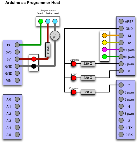
I came to the realization that I had to somehow prevent the host from resetting.  There were two different versions of this that I've found.  One is using a 120 ohm resistor to power, or a 10 uF capacitor to power.  I deicded to combine the two, because why not, and came up with the right top portion of the following diagram:


The right side of this also shows the indicator LEDs, which show what the programmer is doing.  I figured I had to make a board for the reset circuit, I might as well add the indicator LEDs too.  I unfortunately arranged the board poorly.


I later rearranged it to have space on the board for a ZIF socket to direclty program ATMega or ATTiny chips, which I'll show in a future post. (Yes, the layout bugged me to the point that I wanted to rearrange it.)

In any event, using this new circuit was easy.  Plug the board in. remove the 3 pin jumper, dump the ArduinoISP project onto the host.  Then shove the jumper back in place, plug in the target, select the target device type, and shift-click "upload", and I was able to get 100% success rate on every single widget I wanted to program.

The next issue was the crystal speed.  I posted to the Arduino forums, asking how to rebuild the bootloader myself.  Long story short (which you can read there), after some suggestions for replacing crystal and such, which I was about to do, Tom Carpenter responded with not only a compiled bootloader for this specific frequency, but with very detailed instructions about how to get it working.  Thanks again, Tom!

I got this all set up on my system, downloaded the firmware to the widget, then plugged it in through the original FTDI cable I made earlier, and I was able to get the modified blink code above to work, while programming it through the standard Arduino interface without issues!  I then extended the code to read and write serial to control the LED, just to prove that I was able to do everything on this.

I felt that the next important step was what I call "self hosting".  This step replaces the host Arduino, the one that runs the ArduinoISP software, with another D15 widget.  With the help of getting the definition of the board above, this was just as hard as making up a wiring harness.  On this one, since I could disable the reset line by simply disconnecting it, I did this instead.  On the FTDI interface board, there's a small white jumper that I can remove or install if I want to enable or disable the reset from the host computer.

This gets a little complicated to look at, but basically the top D15 connector is the host that runs the ArduinoISP software, and the bottom is the target device that will be getting programmed. If you notice D10-D13 are connected from the target (pins 4-7) directly up to 5-8.  The reset line of the target is connected to D10 on the programmer, so that it can reset the target.


In execution, it's a little easier to understand.  The above shows the FTDI board connected to a USB cable on the left, and the interface board with its white jumper in the top center.  Next is the host device in the bottom right, which contains the programmer software.  Then the center-left connector is where the target plugs in.

I was concerned about the timing being slightly slow (9% as mentioned above) affecting programming of the target devices, but it turned out to not be an issue.  Like the above one, using a shield and a real Arduino, this is also 100% reliable as far as reprogramming target devices.


At this point, it's basically done.  I've fully documented the widgets, I'm able to reliably program them... Next up was to show off a bit.  The first thing I did was the above. I wrote a simple Arduino sketch that rotates the stepper 360 degrees, then rotates it the other direction a random amount, blinking the LED.  I set this on my desk at work with a Tron Light Cycle, using a stepper that mostly worked, just as a slap in the face to them saying "look... these things are actually usable!"


I decided I wanted to play with charlieplexing some LEDs, (article to come in the future), so I made the above interface board (which I could also plug into a standard Arduino for debugging it).  I plugged this one in to a 9V battery, and left it on my desk.  On the display I had it flashing the text "(company name) RULES! !"


All of this happened a couple hours here and there, a few hours at the workbench at home, a few hours at the workbench at Interlock.  Probably 20 hours total, stretched out over a couple of weeks, with the end result that I now have a huge amount of Arduino-programmer-compatible microcontrollers for free!

Soon, I'll tell you about a project to use these things; using dental floss containers as project boxes!


NOTE: There is an addendum to the circuits in this post over here.

Monday, October 22, 2012

User Interface Exploration: Model T Shell

I like retro computers.  A lot.  While working on my BL-328 project, I snagged my old Tandy TRS-80 Model 102 portable computer, to use as a serial console for it.  Long story short, using it as a serial terminal works great, I just had to throttle the baud rate back to about 1200 baud so that it can keep up.


Because of this, I decided to get back into playing with my Tandy 102 a bit, seen above.  I resubscribed to the M100 mailing list, which is associated with the Club 100 "Model T" Users Group.  They nicknamed the Model 100 and 102 as the "Model T", as in the car, which is an appropriate analogy I think.  I had been subscribed to this in the past, and I really liked the people, their attitudes, and their ethics.  It's as though someone freeze-dried a computer enthusiast group from the late 70s/early 80s, and defrosted them now.

One conversation across the M100 email list mentioned doing a modernized version of the Tandy 100 "Model T" shell interface, running on a portable computer that is a modern version of the '100... which I'm sure you realize is exactly in line with where I am right now. ;)  I picked this idea up and ran with it.3

I started by looking at the interface on my Tandy 102 (seen above), and seeing how it works, and the design used.  I also fired up up the Virtual T emulator, which is a bit more convenient than having the real hardware with me.  It looks like this:

It has an 8 line, 40 column LCD display.  It's got the date in the top left, usually "(C)MICROSOFT" in the top right, since the firm/software was written by Microsoft by a guy named Bill Gates or something.  (This screenshot is from the emulator, so it appears a little different than actual hardware.) The memory free in the bottom right, and the Select prompt in the bottom left, so you could just type in your selection.  The middle area lists all of the files and programs in the ROM, mixed together.

I have started up a project on github called "Model T Shell", and have been exploring this.  It is by no means finished, but I thought I'd bring you along while I experiment and hone the interface to something that makes sense and is reasonably usable.

I started out by doing the basics of it.  It uses curses/ncurses/pdcurses, builds with gcc, and works on OS X (command line developer tools required), Linux (Ubuntu tested, requires ncurses), and perhaps in the future, a build on Windows/mingw.

I took the interface, added color, and made it flexible with respect to the screen size.  Top left has the date and time in the same format (No more Y2k bug!).  Top right is version info and username of the person running it.  Middle section is navigated with the arrow keys, selected with "enter".   Select prompt in the bottom left, and "free memory" in the bottom right.  I wasn't sure what to put in the bottom right yet, so that's just a fixed string for now.


I added in a scanner for the current directory, and quickly realized that doing this was a horrible mess. I also had changed the bottom right to indicate what kind of 'thing' the selector was over.  A directory in the above image.


Next, I figured I'd change it so that you had builtin tools in one section, then the current directory in the bottom section:
This wasn't quite right either.  I think the issue was that I needed to separate them by what kind of thing they are, rather than where they're from.  It needs to make sense for the end user with relation to  workflows, or something. (Sidenote: This is exactly why my basement is a mess.  Everything is in boxes based on where they were one or two houses ago, rather than their function.)

Next, I decided to separate it into three sections: Verbs, Places, Nouns.

Verbs are actionable things.  This includes builtin programs and commandables, and current directory's commandables (executables, shell scripts, runnable programs.) Places are basically directory navigation.  Nouns are things that can be loaded, edited, and such (files).

This seems to make sense for using. As you navigate around the directories, everything sorts as you would expect it to.
So... What's up next?

Next I'd like to change it such that the commandables and places have editable lists.  That means that as you navigate around and find verbs that you like, you can add them to your verb list.  Likewise, you can add places that you like to work from and store them there in that list.

I think that I would need to start with just a few commands and places there, and you could add them as you use the interface.  The default commands might be: CONFIG (preferences), EXIT (leave the interface), ADD (adds a selected place or commandable to the lists), REMOVE (removes a place or commandable). As for places, mountpoints, and home directory.)

I also need to figure out how to let you select commandables for different files. I'm thinking maybe keying off of MIME types, or just more simply, file extensions.  That way, for example, you could open .do or .doc files in PICO, but .txt files in VI or EMACS or whatever.

Oh, and it should also probably do something rather than just letting you navigate around the filesystem.

I don't see there being a final product, a single deliverable to achieve on this project... It's more of an exploration of how an interface like this might work for a modernish system.  I'll post an update when I figure things out more.

Thursday, October 18, 2012

Building the BL-328 Computer: Part 1: Introduction and CPU


I recently decided to work on a physically small project. I decided to take the sort of ethics of the classic computer systems from the 1970s, which by design were considered what we now woud call "homebrew" and apply them to modern computing. I tried to keep things as stock and off-the-shelf as possible, so that this was easily reproducible by others.

To me, building a standard x86 PC from boards is not really in the same neighborhood of what I wanted to do here.  I want to do something with the feel of the Apple I for example.  Buying components, making wiring harnesses, writing firmware to control it, and having the primary user interface for it be a BASIC environment, much like the home computers of the 1970s and 1980s.

The name "BL-328" is taken in the same way that the TRS-80 got its name (Tandy/Radio Shack Z80 based computer.) For this, I went with "BL" signifying "BleuLlama", the nickname I use for IRC, and "328" signifying the ATMega 328 AVR microcontroller in the form of an Arduino.

I should note that Ben Heckendorn recently did a similar project, which you can watch his project on The Ben Heck Show.

To follow along with this first step, all you will need for the first step is an Arduino board, available from Adafruit, Sparkfun, Radio Shack, homemade, etc.   The one I'm using is one I bought a few years ago from Sparkfun, the Arduino Pro.


This one has the pin header on the right side there which connects to an FTDI cable to a host computer.  I will also be using this connector to power the entire system through the use of the FTDI-USB cable, AA Battery holder, or rechargable battery pack.

To start off, I took "TinyBasic" which had been ported for use on the Arduino by Michael Field, and I have since expanded upon(github project link).  I have added SD card support with loading and saving, data pin IO, as well as graphic functions specific to this project, but I'm getting ahead of myself.

Downloading that project's TinyBasicPlus.ino to the Arduino will give you a Basic interface with few hundred bytes of program space free.  You can use the "Serial Monitor" which is bundled with the Arduino IDE to interact with it.

The Arduino has 13 digital IO pins, some of which can be used for pseudo-analog output through the use of PWM,  as well as 6 analog Input pins, which can also be used for Digital IO.  A simple program to print out 10 results from Analog input 3, and turn on digital output 5 is as follows: (Note, that this assumes a new feature of TinyBasicPlus, "autoconfigure" is enabled)

10 REM example program
20 DWRITE 5, HIGH
30 FOR A = 0 TO 10
40 b = AREAD 3
50 PRINT B
60 NEXT A

You can write programs that will read port pins, write to port pins, and then load and save to an SD card, if you have FileIO enabled.  The SD interface I went with from this was the SeeedStudio SD Card Shield which was reasonably priced at Radio Shack.  It is hard-configured for its "select" to be on pin 10, which is shown in the TinyBasicPlus.ino file.  You will need to comment out the #undef for fileio and SD card support, and remove the comment for the related #define.  In its current state, it uses the SD library included with the Arduino package, this uses 9k bytes of program space, which is a lot.  I need to find a smaller SD library.

Now that this is enabled, the above program could be saved out to the SD card like so:
SAVE example1.bas

And then re-loaded later like so:
LOAD example1.bas

Recently, a feature was added to TinyBasicPlus that lets programs be autoloaded when you power on.  This is especially useful if you want to write your program (or programs) in BASIC on the device itself, rather than through the Arduino IDE in C.  This is accomplished by enabling the AUTORUN feature in TinyBasicPlus.ino, and by saving your startup program as "autorun.bas".

You can go a step further and have the end of your program "chain" to another program.  That is to say, you could have it load and run another program. eg:

the file "autorun.bas":
10 PRINT "Hello"
20 CHAIN "two.bas"

the file "two.bas":
10 PRINT "World!"
20 CHAIN "autorun.bas"

This will start up, run the "autorun.bas", which will then load the "two.bas" program, which will chain to the "autorun.bas" program, forever.

Enough with the software though.  I'll now get into a bit of the hardware, namely the power system.
As mentioned before, there are a few ways we can power the system.  Currently, since the only interaction you have with it is through the serial port/FTDI interface, you'll have it powered through that, but once we bring this thing into a standalone configuration, we'll want battery power.

The first power pack is a 4AA battery pack with a switch that I picked up from Adafruit. This has the power lines wired to a 6-pin interface like the FTDI interface has.  This lets me use standard AA batteries (rechargable or not) to power the device.

Next up is a USB-based rechargable battery I picked up at the local supermarket for $20.  It's a rechargable (Lithium Ion, perhaps?) battery with Mini USB input for charging, then standard USB for output.  I could use the FTDI cable off of this, but instead, I decided to make a tiny adapter so that I can plug it directly in through the same 6 pin interface:
I have no idea how long either of these will power the system for.  I'm guessing a substantial number of hours.  I've also since made a cable that connects between the battery pack and that header, rather than that little widget pictured above, which is essentially a USB cord whose power lines are wired directly to the FTDI connector.

Using the above, you can hook up an LED to digital pin 5, and do a version of the "Blink" program included with Arduino:

the file "autorun.bas":
10 REM Basic Blinker
20 DWRITE 5, HIGH
30 DELAY 500
40 DWRITE 5, LOW
50 DELAY 500
60 GOTO 30


Then, disconnect the FTDI cable, hook up the battery, and it should blink the LED forever.


That's it for this time.  Soon, we'll convert an old Commodore 64 keyboard into an input device for the computer, add LCD modules for output, and other goodies so that we'll be able to go standalone and not need a host computer at all!

Wednesday, October 17, 2012

Amiga 1000 Repaired!


Amiga 1000 computer (1985) with an Amiga 3000 "pregnant" mouse.
One of the fun things about owning retro computers is that you get to repair them yourself. (Perhaps this isn't a fun thing for some of you, but I really enjoy it.)

About 6 years ago, my Amiga 1000 started showing some strange behaviors but only in the green levels of the video.  If you dragged the green slider, instead of it stepping up gradually from dark to bright, it would get brighter, darker, brighter, darker, much brighter, a little darker than that, and so on. The following video shows this...


About 5 years ago, I had opened it up and replaced two '244 latches in the video output section.  I kinda did this blindly by looking at the schematic...

Video output circuit on the A1000
Left to right: Denise coprocessor, '244 latches, resistor ladders, and output transistors.
...and replacing the two latches, assuming that one of them had gone bad.  After doing the repair, the problem persisted and I just gave up on it for a while.
Green section is at the top.  The two '244 latches are now socketed and replaced.

A few days ago, a comment on the above video re-sparked interest in this project and I decided to bring the Amiga over to Interlock and really get to the bottom of the problem. I hooked it up to a scope and followed the paths according to the schematics.

Amiga 1000 apart, hooked up to a scope and a LCD monitor.
The video circuit is on the left edge of the board, just under the power cable.
I traced the lines from input on Q2 (where all of the four resistors in the D-to-A resistor ladder are joined, and back through to the latch, and then continuing back to the Denise video generation coprocessor.


I tried jumpering across various portions of the resistor ladder to try to track down exactly where the issue was.  It gave some pretty interesting results, but really only helped me track down where the issue is.  I eventually came to the realization that something on the R55 data path was drawing it down to ground, or at least close to ground. (Where the left alligator clip is attached in the above picture.)

The "Green" section of the video generation circuit in
the Amiga 1000 with notes

I tried pulling out the pins on the Denise's G1 output (pin 29) and soldering it directly to pin 15 of U6A, and it didn't change anything.  I then pretty much realized that the issue was on the other side of U6A -- the connection between pin 5 of U6A and the left side of R55 (4k resistor).  I decided to leave the above wire "flying" and pulled the resistor leg, soldering it directly to pin 5 of U6A.

This did the trick!  It worked.  I probably could have restored the flying wire back to the original traces on the board, desoldering the wire, re-seating the chips, but I had flexed those pins in and out a lot, and decided to not stress out the pins anymore, and just leave it.  -- "It works... don't touch it!"


After 5 years of it sitting on a shelf, my trusty 'ol Amiga, my favorite computer, is finally is working again!


Tuesday, October 16, 2012

Puzzle Cube Hacks

There are a lot of hacks of Rubik's style puzzle cubes out there.  Many of them require modifications of the shapes of the pieces themselves, like Tony Fisher's "Fisher's Cube", which rotates one plane of the cube by 45 degrees.  It makes it very confusing to solve.  Similarly is the "Windmill Cube" which also rotates one plane.  Others slice away at portions of the cube to produce a dodecahedron.  (Many of these can be found on TwistyPuzzles.com).

Another modification of twisty puzzles involves restickering a puzzle cube to do things like maze puzzles, color-sudoku, and such.

I decided to do a take on this.  I had a "stickerless" DaYan 2 Guhong "speed cube" that I had bought to see what this design of cube felt like.  I'm by no means a speed cuber, but I figured I'd check it out.  I decided that this cube would be a platform for trying a few different puzzle mods.

Being "stickerless", this meant that each piece's plastic is actually the cube's color (red, orange, blue, green, yellow, white) rather than having stickers applied to a black plastic cube.  I kinda like the look of the stickerless cubes.

The first one I did was to shuffle up the cube, and put stickers (in this case, vinyl electrical tape diamonds) on it to look like pips on a die.  In its solved state, it looked like a multicolored die, 6 opposite 1, 3 opposite 4 and 5 opposite 2.  I didn't leave this cube in this state for very long, as I found that it was impossible for me to solve once it was mixed up.  I cannot find a picture of it.

Next I decided to do something with it that I'm pretty sure hasn't been done before. I made it into an "Inverted" cube.  Rather than it having colored stickers on a black cube, I have black stickers on a colored cube.  Unfortunately, I ran out of black stickers, and had to use purple for the white side, but I've got some stickers on order to replace that and "complete" this cube.


It's a nice fun challenge to only be able to partially see the colors of the sides. I really like solving this one.