Wednesday, March 6, 2013

Anamatronic Avian: Skeleton Experiments

I'm about to start making the skeleton for my animatronic Tiki-Room Macaw.  Rather than futzing with drawing up detailed plans in some cad program, Iv'e decided to instead get the basic shape made, and then just build one out of foam core.  My thought was that once I have the shape worked out, I'll disassemble it and come up with plans for 3d printable parts that can be attached together, and eventually some vacuum formed parts as well for the head and beak, which need to be lightweight... although I'm starting to think that they could all be 3D printed, with a skin stretched over them for feathers and fur, after seeing the posts on Hack-A-Day about using acetone vapor to smooth out parts... anyway..

One of the things I was unsure of was the control linkages, and how the articulation points can be made.  It needs to have a few points of articulation to match the birds in the Enchanted Tiki Room:

  • Perch rotation - 270 degrees, spins the bird around (not shown)
  • Lean - +20, -20 degrees, to lean forward and backward at the point where the legs connect
  • Head yaw - +45, -45 degrees back and forth
  • Head tilt - +15, -15 degrees up and down
  • Beak - 30 degrees, could be all open or all closed (shown in the diagram as 15 degrees)

I was thinking that after I constructed the foam version, I could figure things out from there, but after seeing this post on Hack-A-Day with a "HOG Drive", I realized I could leverage off of this design for the head linkages.

I chatted with Skip at Interlock, and by the end of this past Tuesday evening, I had two 3-D printed versions of this, using ABS, rather than the PLA material I am more familiar with. (Here's the Thingiverse link for the design.) Since I wasn't going to be mounting a motor, we (and by "we" I mean "he") replaced the motor space with a flat plate with a mounting screw hole.  He also replaced the back control arm with just a peg, since the bridge-like shape wouldn't hold up properly on his printer.


The first print (on the left) has a failed control peg on the center disk.  It was adding material onto printed material that didn't cool yet, so it just kinda globbed up.  This was improved by Skip by adding a second post, seen in the second version on the right.  He also added some material around the screw holes in the frame, to improve durability.

After printing and having this in my hand, I'm realizing that it won't quite work for me, although it does give me an excellent starting point.  The center disk is too small to mount the head on.  It's only about 1 1/2 inches in diameter. I think I'd want something about 2-3" in diameter, with plenty of mounting points and space for securing the head ,as well as space for wiring for the beak servo (or linear motor, or solenoid, or whatever).  It really showed me the design considerations for actually constructing something, not to mention it really emphasized that whatever design I can think of, I can print... which is pretty futuristically awesome.

But the important thing is that I know have ideas to build on for the final version.  I'll still be constructing a foam core model, and I'll be using this above design as a kick-off point.

(This post is cross-posted to the Interlock blog as well.)

Monday, March 4, 2013

Arduino EEProm Explorer

NOTE: there would be a screenshot right here, but there's really no point. It'd just be a terminal window showing something like this:
> 
Anyway... while working on the BL-238 uComputer, I wanted to add EEProm support to load and save programs. One of the things I needed was a way to probe into the EEProm to see if everything in there looked correct, or if things were going awry, a way to reformat it and so on.  In the process, I created this EEProm Explorer which is available on github.

It presents a shell interface over the serial connection, that has a few commands that can be typed in.  Perhaps some of you out there can use it to help snoop at the data for your own programs, or whatever.  I may be adding in functionality to this (along with in TinyBasicPlus) to load and save EEProm data directly to SD Cards as well, but that's in the future.

Commands are:

  • format - clear the EEProm - fill it with 0x00 (zeroes)
  • dump - display a fancy hexdump of the EEProm contents, hex values and ascii equivalents
  • print - display the contents as though they were a text file (ascii only)
  • record - capture user input until a "." starts a line.  Great for filling with textual content.
  • poke A D - poke the data value "D" into address "A".   Both values are decimal numbers.
  • ? - display the help message, along with RAM/EEProm sizes.

So, download this sketch to your Arduino, and connect via the serial monitor, and just type in the commands to use them.

Be aware that different micros have different amounts of EEProm storage.  The 168-based devices have 512 bytes, while the 328-based devices have 1024 bytes.  Arduino DUE (Arm CPU) devices have no EEProm (so far.)

Future versions of this may change the builtin commands, or add to them.  (Current version as of this post is v002.)

Hope y'all have use for this little tool!

Setting up and using Arduino as a Programmer


One of the things that I've had to do for my re-purposing of the DB15 Stepper Motor controllers is to be able to reliably reprogram them.  The early versions of the programmer consisted of just a wire harness with a DB-15 connector on one end, and leads that plugged into the headers on a standard Arduino board. It eventually progressed into an octopus-like wire harness that used another DB15 as the "host" Arduino.  This worked well, but is cumbersome.  In this post, I'll highlight the basic circuit used, and the procedure for using it, specifically for this controller board, but the techniques are applicable to other ATmega based micros as well.

The reason for doing all of this work.  About 30 or so DB-15 widgets which can be repurposed as Arduino-compatible microcontroller boards.  They don't have all of the IO that a stock Arduino board has, but if your device only needs 6 IO (one of which is analog input), with a potential for another analog input, and 4 more digital outputs with a little work, they're an excellent free resource at Interlock!


The ICSP (In-Circuit Serial Programmer) is basically a device that takes in a firmware image from a host computer, and uses SPI-based communications with a target device to shove that firmware image into place.  For general Arduino use, you can shove the Arduino serial bootloader into place. This is about 1k (for the optimized bootloader aka "Optiboot") of program space that sits on your micro, next to any sketch that you download to it.  When the Arduino powers up or gets reset, this small bit of code will check for a new sketch to download.  If it sees something, it will accept it, shove it into program memory and then run it.  If it doesn't, it simply skips over and runs whatever sketch has already been downloaded there.

The ICSP allows you to program in that bootloader.  You can also use it to program in your sketch, if you need to reclaim that 1kbyte of space.  I'll get into that later on.

Okay.  Let's get into the hardware for a moment.

Host Connection.
Showing the basic construction for the Arduino-ICSP Host.

Target connection.
Showing how to hook up the D15 to the programming header above.  These 6 lines can also be arranged in the 2x3 layout standard on Arduino boards as well, or wired directly to ATMega chips for other applications.

On the Arduino, the pins are mapped as such:
  • Digital 13: SCLK (Orange)
  • Digital 12: MISO (Yellow)
  • Digital 11: MOSI (Violet)
  • Digital 10: SS (Green) (Wired to RESET for the programmer, DB15 pin 4)


The circuit to wire up is pretty easy.  On the host, there are three status LEDs that the packed-in "ArduinoISP" uses.  Heartbeat shows you it's alive, Programming shows you when it's programming a target device, and Error tells you when something went wrong -- which is also displayed on the host computer.

These three output should be wired through a 220 ohm resistor, to a LED, and tied to ground.

One other thing that may be necessary is to disable the reset circuit on the host Arduino.  This is necessary because when the computer connects to the host Arduino-programmer, that micro will reset, and then quickly hop into the "check for new firmware over serial for itself" routine, as explained above.  This may often cause failures with the host computer connecting and communicating with the programmer properly.  If you disable the reset circuit here, it will never fall into this state, and will remain perfectly stable.  The easiest way to disable it, if you're building it up from scratch, is to disconnect the DTR/Serial based reset trigger completely, leaving the 10k pullup resistor tied to the arduino's reset line.  However, if you're using a pre-constructed Arduino as the host, you can simply tie the reset line to +5v through a 120 ohm resistor.

Connecting the host to the target is also easy.  The target device should be hooked up as a basic arduino -- power, crystal clock, etc. Be sure that even if they're on separate power supplies, that they at least have their grounds tied together.  For ease of use, just power the target from the host completely. Past that, simply connect up pins 11, 12, 13 from the host to the target device.  This will put both on the same SPI bus.  This is how the data will get sent to the target device.  Basically, this maps out as SPI-MISO, SPI-MOSI, and SPI-CLOCK.  The only other connection you need to do is to hook up pin 10 from the host computer through to the RESET line of the target.

Step 1: hook up power, ground, serial IO, and reset circuitry.
The reset circuit is a 10k pullup resistor to +5v, and a .1uF cap to the reset line.
Next up will be putting a jumper to disable the reset line as explained above.
(Note: this picture is from a different build but shows the same first step)

The DB15 as seen here has pin 1 on the right.  The pins are basically: 1) TX,  2) RX, 4) RESET, then +5 and ground on the bottom pins.

The Red LED is the power indicator.  The resistor and cap for the reset circuit are visible, as is the jumper for disabling reset on the ICSP widget.

Above you can see the version of this board that I fabbed up for Interlock.  It has the FTDI header for connecting to the host computer, and used a pre-programmed DB-15 widget with the ICSP firmware on it.  I know this sounds like a chicken-and-egg thing, but once you program your first device using a standard Arduino as the host, it makes sense to program one of these, and use it to replace that board  instead. (especially when you have ~100 of them to spare. hehe)

The blue/white/red/white lines from the ICSP widget are equivalent to pins 10,11,12,13 on a standard host Arduino, and those go right into the cable down to the target device. Since pins 9, 8, and 7 were not all able to be broken out to the LEDs, I had to tweak the sketch a little.  8 is the LED on the ICSP widget itself, which is Yellow.  The Yellow and Green LEDs on the board (along with their current limiting resistors) are wired up to Analog 2 and Digital 3 (pwm), and these ports are changed accordingly.  8 remains as the error LED, 3 became the green Heartbeat light, and A2 became the new yellow program light.

Ready to roll, with a target device plugged in!
Note the extra prototyping area.  This can be for a ZIF socket in the future for other devices, etc.


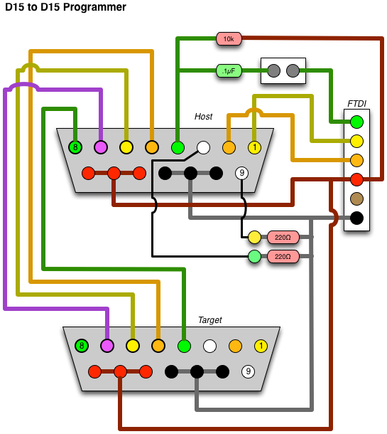
The full circuit diagram for the D15-hosted programmer, connected to a D15 target.
(The wire colors are the same as the above for reference.)

Once this is all wired up, we can get some firmware down onto that thing.  In our case, we have a device that isn't directly supported by the Arduino IDE, so we need to configure that first.

Two things need to be installed. First is the board definition, second is the optiboot hex file. Both of these content files can be grabbed from my Geodesic Sphere repository.  Full instructions are also there as for specific directories on Windows and Mac for doing this installation. The "readme" there shows the text block to drop into your "Boards.txt" file, and where to find that file.  You will also need to drop the optiboot.hex file into the "optiboot" folder as well.  Once these two steps are done, you can start up the Arduino IDE and you're ready to program.  Let's also assume that we've already externally kickstarted this, and the "Arduino ISP" sketch is already on the host device, and is running properly.

Here's where it gets confusing.  What? You're not already confused?  HERE WE GO!

Fire up the Arduino IDE, and let's set it for the D15 device.  From the "Tools" menu, select "Serial Port" and select your FTDI interface's serial port name.  Next, from the "Tools" menu, select "ATmega168 at 7372800Hz (D15)" from the "Board" menu.  This will tell the IDE what our target device is.  Now, from the "Tools" menu, select "Arduino as ISP" from the "Programmer" menu. This is all one-time configuration stuff.  Now, you can plug in a target D15 widget to the end of the cable seen above, and then select "Burn Bootloader" from the "Tools" menu.  A bunch of lights should flash, and you'll end up with the Arduino bootloader on the target widget!

On the above setup, it's wired such that you can also use it to test the target.  Disconnect the FTDI cable, disconnect the ICSP widget, and move the newly programmed device into the DB15 connector on the board.  Adjust the jumper so that "RESET" is enabled.  Now plug the DB15 cable back in.  This is now the equivalent to using the DB15 as a barebones Arduino.  Load up the D15_Test sketch included in the github repository mentioned above.  Click the "upload" arrow button, wait a moment, and the LED on the target widget should be blinking.  That's it!

One alternate way you can use this is to program your Arduino code onto the target widget without installing the bootloader.  These widgets use an ATMega 168, which has very constrained space, so this might be preferred for larger programs.

Hook it back up in the programmer configuration, with the ICSP widget on the board, the target on the cable, and the jumper set to disable RESET.

From the Arduino IDE, instead of just clicking the "upload" arrow button, hold down the [SHIFT] key, and the text will change from "upload" to "upload using programmer".  It may take a moment longer, but the end result is that you will see the LED blinking on the target widget.

You can use this to program other Arduino-like devices too (ATMega, ATTiny, etc).  You will just need to breakout the 6 lines (MOSI, MISO, CLOCK, RESET, +5v, GROUND) to whatever pin header configuration or socket is necessary.  Then you can just select the target device from the menu as appropriate (ATmega 168, 328, 5v, 3.3v, etc) and then select "Burn Bootloader" from the menus as above, and it will put the appropriate serial bootloader onto the device for you.

Saturday, February 2, 2013

Tron Arcade Lighting Effects 1: New Hardware

As seen in a previous post, I have a Tron Mini/Cabaret arcade machine.  I used to have a Tron full-sized (FS) machine, but sold it many years ago.  One thing that the FS had over the mini was lots of extra lighting.

It had artwork beyond the monitor lit with a regular light, it had a blacklight above the control panel to make the traces glow, and make the joystick glow.  There's also a second blacklight below the control panel to backlight the bottom portion as well.  All of these lights are always lit, making the machine extra awesome.  On the mini, there is glow artwork, but no light to illuminate them.  Ever since the late 90s, I've had a plan to change this, so I bought a pack of UV LEDs, but they've sat dormant in my parts bin until now!

One thing that I'd like to bring to this, is to go an extra step, and bring some ideas over from the "Environmental Discs Of Tron" (EDOT) machine.  On the EDOT, you walk inside of it... one of the few, if not the only, games where you can do this.  Around the monitor and control panel are lights, similar to the FS Tron. However, on EDOT, they're controlled by the game.  They will flash and such when certain game events happen. I can make this happen with Tron, using an interface to the game, and a ROM hack.

Above all, the modifications made must be reversible.  I do not want to inflict any permanent damage or changes to the cabinet.  I will simply add lighting, make a ROM hack to control the lights, and mount an additional board inside the cabinet.

To start with, I need a secondary micro to control the lights. I'll use one of my stepper motor controller/Arduino devices. I made the FTDI programming and power interface seen above in about 30 minutes on the piece of strip board at Interlock this past Tuesday.  You can see the resistor/capacitor pair to handle the programmer's reset, power, and TX/RX lines, and a red power indicator LED for the heck of it.

After a bit more work, I had the 3 LED driver chips wired up, with their 8 outputs, along with the 5 pin header which I'll be using to interface it with the arcade machine.  The pinout there is two bits of input, 5v power input, and ground.  I'll add in SPI-like (clock+data) communications from the TRON game.  I figure that the first version will just send down a packet stating the lighting effect, but in the future I can use this to send down high scores as well, which can be sent out via serial to a host PC and post them on the net or something like that.

At first it didn't power on properly, and the LED driver chips got VERY hot.  Then I remembered that the circuit diagram I was referring to while soldering this up was incorrect and had power and ground reversed to the chip.  I also had + and - wired backwards for the LEDs as well. I forgot that these driver chips sink current, rather than sourcing it.  After a little bit of emergency soldering, all of that got worked out.

I've since cleaned up the wiring a bit, adding some insulation.

I decided to wire up the LEDs such that the current limiting resistor was wired up with the LEDs, rather than on the main board.  I'm glad I did this, as the resistance I picked (220 ohms) was way too high.

Enhanced image. It sadly doesn't look quite this intense in person.

Experimenting with how it will look to have LEDs inside of the joystick to illuminate it.

The output from these LEDs was much dimmer than I was hoping for. I will be experimenting with lower-valued resistors, as well as possibly doubling-up LEDs for lighting the various artwork elements.  I also need to figure out how to mount the LEDs without damaging the machine at all.

Next up is the ROM hack to talk with this!

(NOTE: This article has also been published to the Interlock blog.)

Monday, January 28, 2013

Inverted Colors Cube

Back in October, I first posted about my Inverted Color Cube.  It's basically a stickerless DaYan Guhong, which has colored plastic instead of black with colored vinyl stickers on it.  In this case, I put black stickers on it.  So rather than getting squares of color, each framed in black, you end up with squares of black, framed in a color.  I had run out of black stickers when I originally made it, and only recently placed an order with Cubesmith, including a bunch of black stickers.  I was finally able to finish this sticker-mod!


I think it looks awesome, and it's a lot of fun to play!  It's not too much of a challenge, but it's certainly a nice change!

Here are some of the sticker sets I just got from Cubesmith.  Each of the sets was only $2.50, and arrived in about two weeks.  If you plan on doing this with your cube, be sure to get the plastic scraper tool thing.  It's essentially a plastic razor blade, perfect for removing stickers.


Also in the order were a few sets of other stickers.  The top set is the vinyl "Studio" color set.  The colors don't really translate well here, but the blue is a dark blue, the green is a regular green.  Also, in person, the difference between the red and orange is a lot more obvious.

The bottom row is the vinyl "Half-Bright plus Bright Blue".  The green is more fluorescent, and the blue is noticeably brighter than the above.


Here's the vinyl mosaic set.  There's no green, but there's a pink set instead.  The red and orange are about as similar as they appear here.  Also the white/silver is prismatic, while the gold is just circular-brushed.  I'm not sure I like this set all that much.


I also got some extra white/silver prismatic vinyl stickers, the stack of black stickers, one set of which I used on the cube at the top of this post.  Then the bottom six are the vinyl "Chrome" set.  Silver, Orange, Green, Gold, Red, Blue.  They look really pretty in person, nice and metallic shiny looking.


And here is my Zhanchi restickered with those chrome stickers.  The thing is brilliant.  The funny thing is that in person the red and orange are very distinct, and the silver/gold are difficult to see... the opposite of this image.  But man...SHINY!  I'll have to be sure to always put it in a carry bag so that it doesn't get scratched to hell. hehe.

Thursday, January 24, 2013

D15 Stepper Motor Reset Fix

One minor change I just figured out to my stepper motor to Arduino project from before, in relation to the wiring for the reset portion of the circuit.  I was having issues with programming these, once the Arduino firmware was on.  They wouldn't always reset properly when sending down new firmware via the Arduino interface.  I just looked at the circuit for the Arduino itself, and realized that a 10kΩ pullup resistor was missing from the circuit.

All of the circuits on the main page, as well as on the daisy chained serial project need to have the 10kΩ resistor added for proper functionality.  The resistor is essentially tied from +5 volts to the reset pin, pin 4 of the D15 connector.   It's a cheap and easy fix, which lets these things work oodles better!

Addressable LEDs


I'm in the process of constructing/setting up my office in the house, and for lighting, I have decided that I want to use xmas light-style lighting.  Many years ago, I used to light my room with multicolored incandescent lights. I loved the warm indirect glow, and smooth light without a single light source.  This time, I'm going to take it a step further.

While there's nothing about this project yet that is really innovative over what others have done, it is the first step to getting the office lighting done.  The real fun will come into play once I'm able to hang this up, and start programming effects, and tying those effects in to physical or time-based events.

A couple years back I picked up a strand of addressable LED lights, similar to this one, available at adafruit.com.  I got a strand of 50 lights, blew out one of them while being stupid, and used a few of them in Jasper's Toy Box (posts to come about that eventually), so I'm left with 42 lights.  A nice number.

In any event, the plan is to hang them up around the upper perimeter of the room, and it will give a nice comfortable glow to illuminate the room.  I can also extend it by doing lighting effects with the color.  For example, in the evening I can have all of them dim blue, and randomly twinkle one to white, to simulate a star in the sky.  I could also tie them in to an automation system to glow a particular corner of the room red or yellow when i have email from a specific person.  I could also adjust their color based on the content of my monitor, or the light outisde, etc.

The basic design for the control circuitry is that there will be an Arduino-based AVR micro (actually one of the D-15 servo controllers I've appropriated), which is perfect, since the strands only need two lines to control them.  The host computer will send down codes to address the LEDs (set all to color X, set led Y to color X, etc) and this will pass on the content to the strand, and twiddle the data lines and all of that fun stuff.  I had considered putting more "smarts" into the micro, but the amount of space in there would severely limit the kind of content I could "display", so I decided to put all of the grunt work back on the host computer.

To power it, I needed to get a 5 volt power supply. I snagged a power brick from an old external drive case, as well as a standard PC power connector, from a failed power supply, and spliced the two of them together.

Copious, yet appropriate amounts of heat shrink tubing and splicing some wires yielded a nice power supply.

Next, I built an interface board to tie it all together.  The ports on the board are (left to right) - 6 pin FTDI interface for serial IO, 2 pin jumper (power the D15 from the power supply rather than FTDI source), 3 pin power, 4 pin light strand connector.  You can also see in this picture, the process of crimping the terminals for the molex connector on the LED strand's wires.

I kept the layout and pinout of the FTDI the same as I used for my serial node experiment.  This will help me plug that connector in correctly.  I still need to add visual cues (colored sharpie markings) to help me align the pins correctly.  The power connector has GND on pins 1 and 3, and +5V on pin 2.  Keeping it symmetrical will help me always plug it in correctly, reducing the chance that I will blow it all up.  The 4 pin connector is the same pinout as the wiring of the LEDs.  GND, Data, Clock, +5.


The jumper on the board (dis)connects the power header from the D15 and FTDI portion.  If I make standalone firmware for it, I can power everything from the power supply, if need be. The tiny green LED on the board just lights when the D15 has power.  A nice indicator in case everything else is not functioning.

The protocol I used for this is very simple.  There's a command character sent through serial, then the data for that command.  If the firmware is expecting a command character but gets something it doesn't understand, it just keeps checking the serial input for a command it knows.  The protocol is as follows:

p<index of LED><red value><green value><blue value>

Five bytes.  It sets the specified LED (0..42 in this case) with the specified RGB value (0..255 each).  Note that this is not an ascii string, it is data.  So no matter what, it is 5 bytes to change a single pixel.

f<red value><green value><blue value>

Force all of the lights to the specified color.  This is handy for clearing everything to black, or flashing/fading effects.

Here's the Arduino firmware used to handle all of this:  (Note: it requires that the strand's library be installed.)

/*
 * Firmware for D15-based LED strand controller. (Arduino.ino)
 * Scott Lawrence yorgle@gmail.com January 2013
 */
#include "SPI.h"
#include "WS2801.h"
/*****************************************************************************
based on the example sketch for driving WS2801 pixels
*****************************************************************************/
int dataPin = 12;
int clockPin = 11;
int indicatorPin = 8; // LED indicator on the D15 node

// Set the first variable to the NUMBER of pixels. 25 = 25 pixels in a row
WS2801 strip = WS2801(42, dataPin, clockPin);

void setup()
{ 
  // set up the indicator for output 
  pinMode( indicatorPin, OUTPUT );
  digitalWrite( indicatorPin, LOW );

  // set up the strip
  strip.begin();

  // Update LED contents, to start they are all 'off'
  strip.show();
  // ready light
  allColored( Color( 0, 0, 0 ));
  setLED( 0, Color( 0, 255, 0 ));

  // start Serial IO
  Serial.begin( 9600 );
}

// Create a 24 bit color value from R,G,B
uint32_t Color(byte r, byte g, byte b)
{
  uint32_t c;
  c = r;
  c <<= 8;
  c |= g;
  c <<= 8;
  c |= b;
  return c;
}

void setLED( int idx, uint32_t c ){
  strip.setPixelColor( idx, c );
  strip.show();
}

int getSerial()
{
  while( !Serial.available() );
  return Serial.read();
}

void allColored( uint32_t c )
{
  int i;
  for (i=0; i < strip.numPixels(); i++) {
    strip.setPixelColor(i, c); 
  }
  strip.show();
}

void loop()
{
  int cmd; int ii, rr,gg,bb;

  // blink the indicator LED
  digitalWrite( indicatorPin, millis() & 0x80 );

  if( Serial.available() ) {
    cmd = Serial.read();

    // current commands:
    // p<index><red><green><blue>
    //     set a single pixel a color
    // f<red><green><blue>
    //     flood fill with this color

    if( cmd == 'p' ) {
      ii = getSerial();
      rr = getSerial();
      gg = getSerial();
      bb = getSerial();
      setLED( ii, Color(rr, gg, bb) );
    }

    if( cmd == 'f' ) {
      rr = getSerial();
      gg = getSerial();
      bb = getSerial();
      allColored( Color(rr, gg, bb) ); 
    }
  }
}

For now, that's it.  I made a simple interface on the desktop side in Processing, adapted from my previous controllable pixel software, to let me click and change the color of an LED. I also added some key commands to do simple effects with the lights. (all red/green/blue. flash, etc)


/*

 * Pixel Strand Driver (Processing.pde)
 * Scott Lawrence yorgle@gmail.com January 2013
 */
import processing.serial.*;

Serial myPort; // comms to the micro
PImage colorsPic; // color wheel image
color lastColor = color( 255 ); // last clicked color
PFont fnt; // font for display

void setup()
{ 
  // setup window
  size(450, 370 );
  // setup serial
  println( Serial.list()[0] );
  println( Serial.list()[1] );
  println( Serial.list()[2] );
  println( Serial.list()[3] );
  println( Serial.list()[4] );
  myPort = new Serial( this, Serial.list()[4], 9600 );

  // setup the pic
  colorsPic = loadImage("color_sphere.png");
  image(colorsPic, 0, 0);
  loadPixels();

  // setup the font
  fnt = loadFont( "Glass_TTY_VT220-20.vlw" );
  textFont( fnt );
  noSmooth();
}

// for main color display
color frameColor;
int selector = 0;
// for effects
float r,g,b;
int flash;

void draw()
{
  // fill with the last color
  background( lastColor );

  // draw the image over it
  image( colorsPic, 0, 0 );

  // draw the "selector" number (0..9)
  fill( lastColor );
  String s = "" + selector;
  text( s, 5, 20 );

  // if we're doing the "flash" animation, handle that now
  if( flash != 0 ) {
    if( flash == 1 ) {
      flash = 2;
      fillPixels( 1.0, 1.0, 1.0 );
    } else {
      flash = 1;
      fillPixels( 0.0, 0.0, 0.0 );
    }
  }
}

void keyPressed()
{
  // key 0-9 picks from the first 10 LEDs to change
  if( key >= '0' && key <='9' ) {
    selector = key - '0';
  }

  // key "a" means that the color picked will affect ALL LEDs 
  if( key == 'a' ) { selector = -1; }

  // key "F" will toggle flashing all of the LEDs
  if( key == 'f' ) {
    flash = (flash == 0)?1:0;
  }

  // keys r,g,b will toggle the mask to full intensity 
  if( key == 'r' ) { r=(r==1.0)?0.0:1.0; sendRGBMask(); }
  if( key == 'g' ) { g=(g==1.0)?0.0:1.0; sendRGBMask(); }
  if( key == 'b' ) { b=(b==1.0)?0.0:1.0; sendRGBMask(); }
}

// for the "full intensity" flags, send that down

void sendRGBMask()
{
  fillPixels( r, g, b );
}

// send down a "fill all pixels" command with the specified color
void fillPixels( float r, float g, float b )
{
  int rr = int( r * 254.0 );
  int gg = int( g * 254.0 );
  int bb = int( b * 254.0 );

  myPort.write( "f" );
  myPort.write( char(rr) );
  myPort.write( char(gg) );
  myPort.write( char(bb) );
}

// send down a "set this pixel" command with the specified color
void setPixel( int index, float r, float g, float b )
{
  int rr = int( r * 254.0 );
  int gg = int( g * 254.0 );
  int bb = int( b * 254.0 );

  myPort.write( "p" );
  myPort.write( char(index) );
  myPort.write( char(rr) );
  myPort.write( char(gg) );
  myPort.write( char(bb) );
}

// on mouse press, set the color under the cursor, and send it down

void mousePressed()
{
  lastColor = get( mouseX, mouseY );
  if( selector >= 0 ) {
    setPixel( selector, red(lastColor)/255.0,
                        green(lastColor)/255.0,
                        blue(lastColor)/255.0 );
  } else {
    fillPixels( red(lastColor)/255.0,
                green(lastColor)/255.0,
                blue(lastColor)/255.0 );
  }
}

// handle dragging the mouse as well
void mouseDragged(){
  mousePressed();
}


Eventually, I will write better desktop software which will use the LEDs for indication of events, as well as f.lux style color effects throughout the day, audio/visual synchronization to media being played, and other effects as well as time goes on

NOTE: All of the source/projects for this are available on github.