I now once again have a map to use! The black circle in the Atlantic is the starting position. The open circles are all of the locations you can visit. (China, Japan, San Francisco, Washington DC, New York City, The Caribbean, England, Switzerland, Greece, Egypt and India.) The black lines are "preferred" ways to go, and the pink lines are unnecessary loops, dead ends, and game-ending branches of the maze
I started with a printout of the image from the previous post, and played the game a bunch just to explore the map. I also started writing down what items you can get from which locations, which I've condensed down into a google sheet which is available as I work on it here.
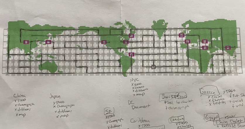
I checked it against maps online, and it seems to be 100% the same as those. I really wanted to make the map entirely by myself rather than using one from the 'net.
Once I mapped it out the entire thing, I re-opened Photoshop and added a new map layer, and reduced down the map to only the segments that I should use in the game... eliminating dead ends, unnecessary loops, and places that will just end the game.
Last night I also played a bit, streaming to my BleuLlama account on Twitch, which was my first time doing that too. I learned a lot about how NOT to do it, and things to improve for the next time I play... I also need to figure out how to get it to record the stream for later viewing.
One of the snagging points was that my disk image for C64 of the game was corrupted, so I also had to track down another copy that worked. I think I'll prefer playing on the C64 because after the game is loaded, the transitions are much quicker than they are on the Amiga version.