Showing posts with label hack. Show all posts

Wednesday, April 29, 2020

Experiments with LANC on my Sony GV-S50 Video Walkman

An Arduino Uno with a LANC interface on a horrible looking shield.

I've been working from home, and I've of course been playing stuff while I work from my LaserDisc player, and 8mm Video Walkman GV-S50 playing some stuff I recorded in the 90s... MTV AMP and a few hours of a local WRUR electronica/trance show called "Digitalis".

Sony Video Walkman GV-S50

But of course, since I've got the deck right here next to me, and it doesn't have an IR receiver or any way to remote control it, I need to solve this major problem. ;D

LANC port is the 2.5mm jack on the bottom labelled "REMOTE"

The deck has a LANC connector on the back, and I happened to find a 2.5mm plug the other day, so this seemed like an obvious thing to do.  Obviously.

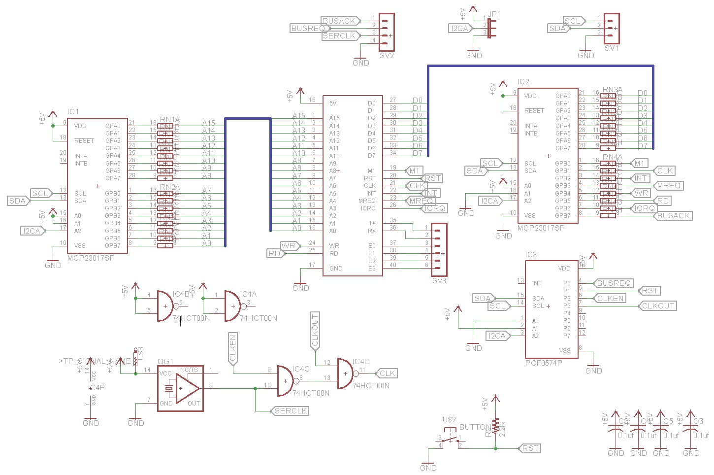
The schematic I based my circuit on. I did not include the 'push rec' button,
and I added a switch between LANC +5 and this circuit so I can decouple the power.
The transistor diagram shows the view of the transistor looking at the bottom of the device.

I found this schematic to interface to the LANC port, along with this arduino sketch that lets you just send the two byte commands out from a serial interface.   Thanks to getting totally confused from the article I found, I re-read through this doc about the LANC commands and figured out that what I need to do is send the standard command byte (0x18) followed by a standard command, and the deck will do what i command it to do!  So I did have it working, and better yet, the deck provides enough current to power the Arduino directly from the port.


My very slightly tweaked circuit

I made a tweak to the circuit just so that I could not worry about the 5V from my computer mingling with the 1990s 5v coming out of the VCR, so I added a switch.  In the pic of the shield above, the blue pushbutton switch can be seen by the second usb port.  That board has been re-used for a few projects, so there's only a couple of components on there that are actually for this one.

The only things on this board that are for this project are the blue switch in the bottom left, the transistor and zener diode in the middle and 4 of the resistors.  The schematic only shows two, but I didn't have a 5.6kΩ resistor so I cobbled one together using three in series.


The docs there weren't complete for this deck (Sony Video Walkman GV-S50), and I found a few more commands (volume, megabass) so I thought I'd put the list of commands here for future reference:

Group: (0001 1000) (0x18) - Normal Command to VTR or Video Camera 

  • 1830  stop
  • 1836  rew
  • 1838  ffwd
  • 1834  play
  • 1832    pause (still)
  • 1840    still
  • 1860    frame reverse
  • 1862    frame forward
  • 1850  search - (scan until 'play' or 'pause')
  • 1852  search + (scan until 'play' or 'pause')
  • 185E  power off
  • 18b4  counter display/data screen
  • 188c  counter reset
  • 18b0  tape speed (LP/SP)
  • 183a  rec  (untested, assumed to work)
  • 183c  rec-pause (untested, assumed to work)
  • 18d0  audio dub? (untested, might work?)
These were not listed on the LANC page, but I poked around until I found them:

  • 1876  megabass toggle *
  • 1824  volume +
  • 1826  volume -
  • 18fc  still/shuttle (still frame)
  • 1846  slow
  • 184c  x9 speed (scan forward)

Group: (0001 1110) (0x1e) - Normal command to still video camera)

  • 1e52  photo preview (scan forward)
  • 1e5e  power off

I tried a lot of the commands with the TV Tuner card installed, and none that I tried seemed to control it at all. (channel up/down, timer functions, menu functions).  In general, none of the menu interaction commands worked at all, sadly, other that direct tape speed, counter reset, megabass mentioned above.

I eventually want to have an IR Receiver module on there, and program it to receive commands from my mega sony remote, but for now, i can type the commands out to the serial port. For example. if I type 1834[RETURN], it is the equivalent of pressing [PLAY] on the deck.

Reference Links:

Saturday, October 12, 2019

RC2019-10 Update 1: A102 Amiga/Tandy/RC2014 Frankenstein

The Enclosure

Since I had started working on this last year, the enclosure is partially completed.  I had removed some plastic ribbing prior to the RetroChallenge, and mounted both a Rasperry Pi 3 and a LL530 keyboard interface board inside of it.  That's about as far as I had gotten last year, so that's a good start. (pics in the next update post)

The Keyboard

I started out with trying to get the keyboard working.  This seems to be the most time consuming portion of the hardware at this point, and has the most question marks associated with it.
The big issue is using the Tandy 102 keyboard with a spare "two header" Amiga 500 keyboard "encoder" board.  I had toyed with the idea of perhaps just wiring up the row/columns to the Tandy keyboard's rows and columns, but this brought up some issues.  Obviously, the matrix would be different... ie; row 2 column 2 would be different keys on the two keybaords.  This would be fine as I could just change the code in the LL530 to convert the fakey-102-500 keycode to be the correct keypress.  I kinda wanted to use the LL530 stock though, so this meant rewiring the 102 keyboard.
The 102 keyboard has diodes at most of the junctions, and there were a different ratio of rows/columns. but I plan on ignoring those by cutting the traces on the board and wiring around them, ignoring them.


I measured resistance for each key on both keyboards.  The Tandy 102 keys ("Alps Mount Round Slider") came out at about 100 ohms when pressed.  The Amiga keys ("Mitsumi KPR Hybrid Switches") were 0 ohms (no resistance).  Could this be an issue with the custom Commodore key matrix scanner on the Amiga encoder board?  Only one way to find out... Wire it up!


I wired up a couple of the Alps keys to the scanner, hooked it up to my LL530 and tried it.  Turns out it all works great, so no worries there! I apparently picked "9" and the left spare key usually between 'left shift' and 'z', which apparently maps to a "section character" (§)


Next, I wanted to try to clean up the keys.  They seem to bind a little as you press them down, as the plastic tube is getting snagged in the mechanism. This is probably due to wear, dirt, etc.  I removed one from the board (four through-hole solder pins), and disassembled it carefully to see what I was dealing with.

The keys popped off using an official key cap removal tool... a pair of tweezers wedged under the key.  Then the plunger and dome could be removed from the enclosure by flexing out the two T shaped tabs on the enclosure top. From left to right: the key cap, top cover (snaps on using the two large T shaped tabs), round plunger, rubber dome with carbonized contact, and finally the enclosure with the contacts in the bottom.


As far as I know, all of the keys are contacting/switching okay, but if i need to replace components, they're easy to swap in or replace the entire key.


I also took this opportunity to replace the "caps lock" and "num lock" keys, which are latching, with two spare keys, since I wanted to reuse the Num key for "right Amiga" and the caps lock key needs to be momentary for the Amiga matrix scanner. The pin layouts were different, so i needed to drill new holes in the board for the momentary switches. The switch labelled "56" above is the replaced caps lock, while "57" is the control key next to it.

Four of the "top row" keys of the 102 keyboard, the arrow keys, don't have quite the right snap/click that the others do, due to 30 years of use and wear.  I happened to have a bunch of exact replacements, which I got on ebay for another project a couple years back, "12x12x7.3mm Tact Switches"


Next is the task of remapping the matrix.  I found some commonalities between the two matrices, seen color coded above... the keys in yellow share the same x/y indexing with the Amiga layout, and the other colors only share the same column.  I traced out the schematic on the keyboard, and cut a bunch of traces.  Next up is rewiring it and wiring it up to the Amiga Encoder board.

More to come....


Friday, August 10, 2018

4 Hour Projects: Adding Video to Interactive Fiction

Overview

After listening to the Eaten By A Grue podcast:19 about the interactive laserdisc-based game for the movie "Rollercoaster", and then following that up with the episode about Hitchhiker's Guide:16, a spark popped in my head. It should be possible to somehow "watch" the Hitchhiker's Guide (H2G2) Infocom game and play clips of the TV show, movie, etc, syncronized to the scenes and what you're looking at.
All of the distributable code for this is available at the github page for the project.
Just about all of this project is based on existing stuff, but I glued it all together.
  • Frotz - runs the Z-code, in a text-based terminal
  • VLC media Player - plays back the video
  • H2G2 TV on DVD - the DVDs
  • Netcat - so my client can talk to the server
  • Tee - to split the output from frotz
  • Perl script (in this repo) - "reads" the text, matches text, tells VLC what to play
The whole thing kinda works, is buggy, unoptimized, but that's the nature of a 4 hour hack.

Architecture

This is the basic system... This was a quick sketch I made to get the idea down. Essentially there are two halves. (I also called it "zvid" instead of "llifvid". pls ign. thx.)

Server/Video player

The server on the left is essentially a perl script that:
  • Matches text from the interactive fiction
  • has a simple interpreted language that can perform sequential functions
  • outputs "remote" commands for VLC
The output of that perl script is piped into VLC. If you're going to reproduce this, be aware that enabling the VLC shell it was a bit tricky, and I didn't document the process. I think I needed to enable extended preferences in VLC to see the bit to turn on that feature.
Also on this side are the video files for H2G2 episodes 1 and 2. I used Handbrake to decode them off of my DVDs. I do know that the episodes exist online, but those may be set up for web streaming, and will need to be transcoded via handbrake or some other tool. It basically just needs to add some information in that isn't there.
Netcat (nc) is setup as a listener for the text output from the game engine. That is piped into the perl script, whose output is piped into VLC.

Client/Game engine

The client on the right is some bash script piping and connection of Frotz with the game file. I used the ms-dos version of the data file, although I do not know if any other versions differ in any way. This was just easiest for me to grab without digging out and setting up my Amiga to pull the files off of my game's floppy.
The output of frotz is piped through tee. Tee takes the output and splits it to two different places. First, is the console so you can see what you're doing, but it also usually saves it to a file. I've changed that path to be piping the output to netcat, setup as a transmitter to the server.

Interpreter

In the perl script is a quick interpreter that I hacked together to run little micro scripts of code. I started doing this as an array of arrays, but if you've ever done that in perl, you'd know that such things are never good ideas in that language. I briefly considered hopping over to python to do it, but I already had stuff done, and was still toying with the idea of having the perl script itself listening to a socket, which i was unsure of how to do in python. So it's in perl.
Anyway, I switched it over to be a plain text blob in the source file. At startup, it cleans up the text, removing comments, and empty lines. It also breaks it up as two elements per line; the opcode and the parameter, and store that as the runtime program. This vastly simplified runtime routines.
The two main entry bits for the language are the label and the text match. It's sort of event driven, sequential language, with no nesting, no calls, no iterations, none of that... one operation per line. I did include comments though which are denoted by pound sign, # and continue to the end of the line. They can be put anywhere, as they are filtered out before runtime.
: label
Labels are used for 'goto' statements, or calling the goto function to set the current PC (program counter). If you call the doGoto() function, it will adjust the PC to the line after that label, or to -1, indicating that it was not found, and there's nothing to do.
? text to match
This denotes text that should be matched. As the program runs, it reads in byte by byte from the client and accumulates it. When it hits a newline 0x0d, or 0x0a, it sends the accumulated text to the "got a line" function. That one tries to match each "text to match" string to see if it matches any part of the current line. If it does, it sets the PC to the next line, and returns.
From there, there are a few opcodes that can be called:
seek 100
This will seek the current video file to 100 seconds in.
until 110
This will wait until the timer hits 110 seconds in in the video. Due to limitations of time, this is implemented as a hack. Instead of looking at the video file to get the time, it remembers the last 'seek' number called, does a difference, and sleeps for that many seconds, blocking. For the above two codes the "until 110" call will essentially sleep for 10 seconds
done
Indicates that a sequence of opcodes is done. "do until done" will stop here" this leaves the PC at -1, indicating it's done.
player play
This sends the "play" command to VLC. It can send anything. Useful things are:
play    # press play on the current videopause   # toggle pause!frame   # advance one frame. forces a paused statestop    # stops the playerfullscreen on  # makes the video full screen (on|off)seek 100 # you can manuall call this as wellrate 2   # twice speed... or "0.25" for quarter speed. etcadd FILENAME   # adds a file to the playlist, and switches to it
These essentially just print out the command, as the VLC shell is consuming the commands directly.

Determining match strings

For this I basically ran "frotz hhg.z3" and copy-pasted long lines of text from the game to match that seemed unique. It worked okay but was kinda tedious.
I was originally going to extract out the room names/descriptions from the z3 files using the tools, but gave up on that for this simpler, quicker approach.

Determining timing

So to get the second counts, I ran VLC, playing the video file, directly: "vlc episode1.m4v", and did a lot of typing in the shell of the above commands. I would type "play" to let it play, then "pause" or "frame" to get it to stop. You can get the current time with "get_time", manually seek to specific times like "seek 300" or differences from the current time, "seek -10" for ten seconds ago, etc.
I could use the GUI for this, but it shows time as mm:ss rathe than time as seconds only.
It was tedious, but it worked. An easier to use mechanism for this would be advantageous.

Conclusions...

So yeah... it worked.  With a lot more work it could be made to be reliable, have a nice editor, and be easily streamlined into more games.  I'd personally want to see an integrated executable as well, to get rid of all of this netcat and shell weirdness, and just have one exe that runs, reading in a language file.  Game packages could be created with the language file, audio, video, etc.  But I feel like I've accomplished what I wanted to for this. 

Saturday, July 28, 2018

Digital Logic in Javascript...


I needed some time off from my main project right now, and I had this bug in my brain to try out some of this, so I did a thing.  It uses javascript, jquery, bootstrap, and css stuff to do the whole thing. I use some of this at work, so this was a great chance to learn a bit more about that tech.

So here's a link to the quickly and horribly named "Logicr", pronounced "lä-jik-ər".

It's essentially a tiny javascript library/set of classes that simulate digital logic.  I'm not going to start drawing out diagrams of class hierarchies because that would take too long to do.  Instead, i'll quickly explain a bit of it, and then explain what the interface is showing.

At the bottom level, there are objects that are "pins".  This is a thing that can be set with a low, high, or floating data level.  I made the level actually a value from 1-100, below 25 is "low", above 75 is "high" and in the middle is "floating".  When you read them, you get back a true/false value, and you can write the 0..100 level, or true/false.  I made it this way so that i can eventually simulate pullups/pulldowns in the circuits.

Those pins are included in "nodes", which have a collection of inputs and outputs.  One example of a node is a logic gate.  A typical gate has two inputs, A, B, and one output, Y.  When the nodes get their update() call, they do whatever math is necessary to read in from their inputs and set their outputs.   Currently the system supports the basic 1-2 input logic gates: Not, And, Nand, Or, Nor, Xor, as well as one-pin output "sources" that generate High, Low, and Float output.

Another node is a "clock".  This one toggles its output once a second (1000ms) between high and low levels.

Another type of thing in the system is a "wire".  Wires are just lists of connections "from" and "to" pins on nodes in the system.

In the above example, there's a clock node (XTAL1), whose output Y goes to the first LED, named "clk".  There's a second wire from XTAL1's output that goes to the input of a Not gate (Inverter), in-turn, whose output goes to the second LED, "!clk".

You may notice that they don't change instantaneously.  That's because the system is set up to update all of the nodes first, then update all of the wires.  This prevented having to actually generate a real directed graph, and deal with loops and recursion and loops and recursion and stuff.  It probably simulates propagation delay on real parts, but i'm sure it has its own unique quirks.

So every 50ms, it goes through and tells all of the nodes to do their math, then immediately goes through the list of wires, reading from their FROM and writing to their TO.

So for the clock circuit:

  • Nodes:
    • Clock XTAL1 running at 1000ms
    • LED D1, blue, labelled "clk"
    • LED D2, blue, labelled "!clk"
    • Not gate IC1
  • Wires
    • XTAL1.Y to D1.A -- connects the clock to the first LED
    • XTAL1.Y to IC1.A -- connects the clock to the not gate
    • IC1.Y to D2.A -- connects the not gate to the second LED

That's the basics of it.

But there's more.

I added a few input devices and output devices.  First is the switch.  The switch is essentially a html checkbox at its core.  When the switch node gets called to update, it reads the value directly out of the checkbox widget in the browser, and sets its output pin to the appropriate value.  Similarly, the LEDs are just a "div" that's made round and the right color (dim/bright red, etc) via CSS.  When the LED nodes are updated, they read the value from their input pin, then apply the appropriate "on" or "off" class to their html div.  The browser and CSS take care of the rest.

There's a couple other things happening in the circuit there too...

The amber switches are the A and B inputs to an XOR gate.  The A and B switches also go to the amber LEDs with the same labels, so that you can see what's going on there.  The output from the XOR gate goes to the green LED labelled Y.

The four red switches labelled 0x01, 0x02, 0x04, and 0x08 are run into a sort-of ROM, implemented as just a simple 16 value lookup table.  The ROM has 4 inputs and 8 outputs.  The 8 outputs are wired to the red seven-segment display node's "a"-"g" inputs, which light up the segments of the display on the web interface.  As you toggle the switches, the appropriate number is displayed.  The ROM data is basically a lookup table of which segments to drive for each value 0x0..0x9,0xA-0xF.  The equivalent of the 74LS47 ic chip.  I was originally going to build this circuit using logic gates, but it got really complex...  I may still do it eventually, once i have a better editor.

Mess with it...

In the interface, if you scroll down, you'll see an editor section at the bottom. Press the "Load Default" button to fill the text box with the circuit description that's running, and you can see all of the logic nodes and wire connections. Press the "Run Circuit" button to read in the JSON content from that window and rebuild the internal logic to use it.  The content there has to be valid JSON, otherwise it won't work.  The "Run" button will have a green border when it's valid, red when it's not.

Future

So yeah. This was meant to be a quick test to see how well it could quickly be done, and expanded upon for a possible future project that I've been thinking about for a while. There are still more component classes I want to add, such as "packages" which can group together circuits... for example, creating flip-flops using gate logic, or building that 7-segment decoder, or more complex things...

I also would like to make an in-browser editor of the circuits.  I've been looking at jsPlumb as well as a few other solutions for doing "create movable boxes with connection magnets that are connected with wires" type of things.  I may just spin up something of my own, as having draggable boxes is fairly easy to do using CSS/JS and then connections are just SVG lines between them, etc...  Although i'm sure the nuances of the interface make it more complex than it seems...

Oh. and this is running in my tiny page thingy, llmin... It's basically a wrapper for a page that sets up jQuery, bootstrap, and some other stuff, so that I don't have to create that boilerplate every time I want to make a page to test stuff. ;)

Tuesday, September 26, 2017

Arduino-Midi for Sim City Music Playback...


Roland Sound Canvas SC-55, hooked up through a hacked cable to an Arduino Uno,
which is connected to... NOT THE MACBOOK because I FORGOT
THE STUPID USB-C ADAPTER AT HOME. GEEZ.

Was thinking in the car on the way to Interlock of a way to make the Sim City 2000 music thing better.

The project I'm talking about is to play the weird Sim City 2000 midi files at random intervals throughout the day, so that life feels more like Sim City. ;)

I have a python script that will play the songs on my laptop... (see below) but I want something more physical..


Roland MT-90. It plays midi files off of floppy disks to a builtin Sound Canvas.
Yes. I think it's a weird thing as well, but at least it sounds nice!

Was thinking of putting an Arduino inside of the MT-90, which would press the button sequence to: (switch on shuffle mode), (switch on random play), then (wait) then (play the next track)... (The arduino would press the buttons via relays, the way I did it inside the Yamaha Tape deck..

I was thinking that it might be nice to not have to hack the device, and have just a midi thing i could plug in to any midi device... I'd have it do the above with the MT-90, but it doesn't have any midi control sequences to control playback... just midi notes/tone generation stuff.

Then I took a step back and thought that if i just stored the midi files on a sd card, and just had the arduino play them itself out to a sound canvas, that'd do the trick! I found a 5 pin din cable, hacked in connections.... but I forgot my USB-C to USB adapter at home. Dang!

So it's not really a failure of a project *YET*, but it was a definite lack of success...

Here's the python script. It expects to be run on a Mac, with timidity installed, which will play the music. Also it expects the midi files to be in a "SC2000/" subdirectory. It's not the most elegant thing, but I hacked it together in a couple days...


#!/usr/bin/python
#
#  an attempt to make real life more like playing SimCity
#
#  It picks a random amount of time from 15-90 seconds
#  if there's silence for the entire thing, it will pick a random 
#  track in the SC2000 directory and play it.
#  then it repeats... until you ctrl-c out of it
#
#  v2 2017-07-28 - made more configurable, quieter output, class
#  v1 2017-07-27 yorgle@gmail.com
#
# Requires: - timidity to be installed (brew install timidity)
#   - OS X (10.12 tested)


import sys
import os
import time
import random
import subprocess
sys.dont_write_bytecode = True


class SimMusic:

# defaults
midicmd = "/usr/local/bin/timidity --no-loop {} 2> /dev/null" 
mididir = "SC2000/"
silenceTimer = 0
timerMin = 15
timerMax = 90
disabled = 999999
timeout = disabled

# constructor
def __init__( self, tmin = None, tmax = None ):
if( tmin != None ):
self.timerMin = tmin

if( tmax != None ):
self.timerMax = tmax

self.setupTimer()

def setupTimer( self ):
self.silenceTimer = 0
self.timeout = random.randint( self.timerMin,  self.timerMax )

def resetTimer( self ):
self.silenceTimer = 0

def stopTimer( self ):
self.silenceTimer = 0
self.timeout = self.disabled

def systemIsPlayingAudio( self ):
process = os.popen('/usr/bin/pmset -g' );
text = process.read()
process.close()
if( "coreaudio" not in text ):
return False
return True


def playRandomMIDI( self ):
self.stopTimer()

files = os.listdir( self.mididir )
fname = self.mididir + random.choice( files )

print( "Timidity: {}".format( fname ))
process = subprocess.Popen( self.midicmd.format( fname ), shell=True )
process.wait()

self.setupTimer()


def run( self ):
playingTimer = 0
print( "scanning..." );

self.setupTimer()
while True:
if( self.systemIsPlayingAudio() ):
if( playingTimer == 0 ):
print( "\n" )
sys.stdout.write( '\033[2K' )
sys.stdout.write( "\rAudio is playing... Waiting. ({})".format( playingTimer ))
sys.stdout.flush()

time.sleep( 1 )
playingTimer = playingTimer + 1
self.resetTimer()
else:
playingTimer = 0
if( self.silenceTimer == 0 ):
self.setupTimer()

self.silenceTimer = self.silenceTimer+1

if( self.silenceTimer > 0 ):
if( self.silenceTimer == 1 ):
print( "\n" )
sys.stdout.write( '\033[2K' )
sys.stdout.write( "\rShhh! {} of {} seconds has passed".format( self.silenceTimer, self.timeout ))
sys.stdout.flush()
if( self.silenceTimer >= self.timeout ):
self.playRandomMIDI()
self.setupTimer()
self.silenceTimer = 0
else:
time.sleep( 1 )

################################################################################

# put this in your main app as well.
if __name__ == "__main__":
simMusic = SimMusic( )
simMusic.run()

Friday, April 28, 2017

Building some RC2014 upgrades...


I've been working on upgrading my RC2014 Z80 computer for the past few months, but in a very low-impact-to-my-finances-that-can't-support-it-otherwise way.  This post will just go into explaining a few of the upgrades I have in mind,

First of all, my current hardware scheme, the "RC2014/LL MicroLlama" as I call it, is and has been fully functional in its current state, and is emulated well in my emulator.

I started working on a mass-storage solution for the MicroLlama, which I have slightly back-burnered this month so that I could attempt to focus on the 2017-04 RetroChallenge ("The Andy Project"), but I'll likely pick it up again next month, especially with some of the upgrades I now have in my hands, which I will now briefly talk about...

Dr. Scott M. Baker's Bus Supervisor Board

A ton of chips and a well packed board!
I just received a "kitted" version of Dr. S.M.Baker's RC2014 Bus Supervisor board. Major kudos to Rob Leisenfeld from the RC2014 community...

The short description of this is that it has some I2C I/O Expanders that sit on the entire bus (Data, Address, Control) as well as replaces the system's 7.37 Mhz clock board.  This can be used to snoop on the system, read/write IO, read/write RAM, etc... taken one level above that, you can use SMB's python scripts to upload data right into RAM, thus eliminating the need for a ROM module.

People have successfully used this to run 64k RAM-only RC2014 computers, and upload the program ROM from their Raspberry Pi. (Schematic, GitHub link to software)


It took me about 15 minutes to figure out the orientation of that crystal.
(Pin 1, the pointy corner, is in the bottom right)
Also, I'm not sure the jumper configuration is correct yet.
That's where my personal problem with it comes in.  As it stands, his project uses a RasPi to communicate with the board over I2C.  This is fine, however it does not fit within my workflow.

I do not really have a RasPi to use for dev work, so my solution is to take a tiny Arduino Leonardo clone ("Micro-SS" like this one), with a cable connecting its I2C lines to the Bus Supervisor Board.  Then, I'll make a thin Serial-I2C bit of software and making some desktop tools, perhaps in python to fit with the original from SMB.
My "proof of concept" for USB-I2C communications.
Here it's connected to an RGB color sensor.
The end result is that in my Z80 project makefiles, i can add a target for the generated .HEX files to be downloaded directly to the physical RC2014.

I've made a cable for my Micro-SS and have built my Bus Supervisor Board.  As you can see in the photo, this is it set up on a powered RC2014 backplane with only the standard IO module, and a few LEDs on a few data lines, so that I can test out everything before putting the CPU and RAM on there, potentially damaging them.

Obviously, it would also be possible to include a couple of ROM programs directly into the MicroSS, and possibly store a small one in the ATmega 32u4's EEprom as well.  Some buttons on the MicroSS could be used for injeting these pre-stored programs.  i could even see a program that generates a menu that the arduino can basically farm out to the Z80 to get user responses/menu options, etc.

Additionally, I can make a RC2014 bus - to - pac-man bus adapter, and actually deploy code-in-development directly to the machine from my desktop from the makefile/build scripts.  ... This is a dev tool I've wanted for about 20 years now!

Lots of possibilities!

I will put out another blog post and a github link for the supporting software, when I've got this working. (estimated - mid next month)

64k RAM and Pageable ROM

I also received this past month the boards for these two official RC2014 boards: the 64k RAM and Pageable ROM.  As you can see in the pic, i still need to order quite a bit to make these work.  Now that I have the Bus Supervisor board, the Pageable ROM is less interesting to my needs, although I may still adapt my RC2014/LL design to use these pieces instead.

You can see pics of these in the top of this blog post.

The 64k RAM will definitely work well with the Bus Supervisor board, however the Pageable ROM board has definitely taken a bit of a slip down my plate... Until I can get the parts in for the RAM (sockets, etc) I can use my existing unmodified 32k RAM board for the upper segment of memory ($8000-$FFFF) and my slightly modified second 32k RAM board for the lower segment of memory, I just have to manually enable it for read/write.

Monday, December 5, 2016

RC2014/LL Showing ROM/RAM switching, 64k!

So I thought I'd just make a quick post to show how I know that the ROM swap hardware in my RC2014/LL is working. I'll walk through the procedure here...

First, I booted up the RC2014 as usual, which drops me into BASIC.  From there I wrote this short program:
10 FOR A = 0 to 8192
20 B = PEEK( A ) 
30 POKE A, B40 PRINT A 
50 NEXT A
What this does is goes through the lowest 8 kbytes of memory, reads (peek) and then writes (poke) the byte it finds right back to the place it got it from.   For example:
  1. Read from memory address 0
  2. Write to memory address 0
  3. Switch to the next memory address, repeat 
Which seems stupid, that it does nothing.  But if you remember from a previous post, when the ROM is enabled, it's only enabled for reads.  Writes still happen to the RAM in the same addresses.  So the above program copies the BASIC ROM into RAM.


Next, we switch off the ROM by doing this:
 OUT 0,1
The lowest bit, '1' turns off the ROM, and switches to the RAM for read operations.  To confirm we're working out of the RAM, we can poke a 0 in somewhere down there.

PRINT PEEK( 0 )
 243
POKE 0,0
PRINT PEEK( 0 )
 0
So we can see here that memory address 0 has been changed from 243 to 0.


I also went one step further and yanked the ROM board out of my RC2014.  This is not recommended. ;)  But it did continue to run without any problems... until I really tried to muck things up, for fun:

I wrote a program to clear RAM, and then ran it in BASIC.  Here is the listing:


And here's what happened when i typed 'run'.  It completely locked up after it printed the '8'. Starting at memory address 0x0008 is the text output routine, so it cleared out the boot code before that (0x0000-0x0007), erased the beginning of the print handler, then went to print out something to the screen, and crashed.  Well, I assume it crashed. It got an invalid opcode and who knows what it's actually doing. The code there used to be a "jump" which is 3 bytes.  Instead it got a NOP, which does nothing, (0x00)  and then two garbage bytes which map to something incorrect. Boom!


Sunday, October 2, 2016

RC2014/LL and RC2016/10


The RetroChallenge is upon us again!

This time around, I plan on working on my Z80 homebuilt computer, the RC2014.  (Website for RC2014, Order a RC2014) For a few months now, I've had my RC-2014 computer built, and modified to be an RC2014/LL computer. What this means is, is that I have some modified modules using no additional external hardware.

The above picture shows my RC2014/LL system with its extra RAM module, and the C0 Serial expansion board to the left, with the SD card interface board (SSDD1) on it.

The basics of this design:

Unmodified RC2014 modules:
  • Z80 CPU module
  • Clock module (* see below)
  • Serial console interface
  • RAM module (for RAM in the range $8000 through $FFFF
Modified RC2014 modules:
  • Second RAM module
  • ROM module
  • Digital IO module
Additional hardware:
  • Second ACIA Serial port at $C0
  • SSDD1 (Serial SD Drive)
(*) While the clock module is unmodified, it technically is modified. I have added a 10 uF (50V) cap between the reset line and ground to be a quick-and-dirty power-on reset circuit. It works perfectly.  Every time I power on the computer, it "presses the reset button" for me. ;)

The plans to mod these parts are available here.  This is currently fully functional and tested. The modifications use unused gates on the boards, so that it requires no extra additional hardware or boards to implement. The basic theory to the /LL modifications are as follows:


Bit 0 (0x01) of the Digital IO module is tied to one of the extra bus lines on the backplane.  Let's call this "Extra-A".  When you do an "out" to that port of "0x01", it will trigger the Extra-A line.


The ROM module "out of the box" is configured such that if there is a memory access, which is a read from address $0000 through $7FFF, it will enable the ROM, and it will put its data on the bus.  My modification adds in one extra condition to this.  It adds in that only if the Extra-A line is LOW, that the ROM will be enabled.  This means that when Extra-A is 0, the ROM works. When Extra-A is 1, it's as though the ROM doesn't exist.


The RAM module "out of the box" sits at the high half of memory space ($8000-$FFFF), and is always enabled on memory READ or WRITE to those addresses.  The modification to this module is threefold.  First, it sits the RAM at the low half of memory space ($0000-$7FFF). Secondly, it is set up that WRITEs to this memory space will always work, regardless of Extra-A.  Thirdly, it is set up that READs to this memory space will ONLY work when Extra-A is HIGH.

The end result of this is that when Extra-A is low, reads in the low half of memory will come from the ROM.  When it is high, reads will come from RAM.  Writes ALWAYS go to RAM.

This is quirky...

I admit this.  It means that you can (and I will) write a bootloader/monitor ROM that is enabled on power-on, will read from a mass-storage device and write into anywhere in RAM... It can load a 64 k byte memory image into RAM, and then switch off the ROM and it will all work.  The quirkyness is that you cannot verify the loaded-in memory in the low range of ram, since reads will come out of the ROM.   Obviously, you also need to do this routine completely out of registers, as your stack variables will get overwritten if you're not careful.

Anyway....

If you want it to behave like a stock RC2014, remove the jumper from the IO board to Extra-A, and instead add a jumper from ground to Extra-A.  I have added a switch to mine to force this in the case where the IO board comes up in the wrong state.

Additionally, I have added a second serial port, which basically follows the circuit for the first port, but it sits at $C0, and does not have an interrupt line wired to it.  The RX/TX on that one comes out to a FTDI-like pinout header, which is where my SSDD1 module plugs in.  The plans for this serial port are available here, and can be seen as the brown perf-board on the left of the topmost image of this post.

The SSDD1 module...


The Serial SD Drive module is the mass storage module that I've created for my Z80 to interface with. I know that I can push the FAT filesystem support onto the Z80, but that would require substantial effort.  I instead decided to go with the model where I have a smart serial-based device that you tell it "i want this file" and it sends it out.  Like a local BBS. ;)

The use of a serial-driven drive is not unprecedented.  It's somewhat modeled after the Commodore 64/Vic 20's "IEC" serial interface for floppy drives.  It also mirrors it in that the drive has some smarts in it to deal with the drive architecture.

I also went this route for the ultimate form of this computer, which is to run CP/M.  CP/M expects drives with a Drive+128 byte Sector layout.  While other Z80-CP/M computers implement this by having direct interface to the sectors on the spinny disk/cf/sd card, I will do it by having files on the SD card, for the most amount of flexibility.  There will be a "drives" folder on the card containing folders named "A", "B", "C", and so on.  These letters are the drives.  In each of those will be directories for the tracks, named "0000", "0001", etc and in each of those, files named "0000" "0001" "0002" etc. These files are the simulated sectors on the disks.  It will be easy to build virtual drives for other use out of this.  It also means that I won't need some special interface on a modern computer to talk with this.  I won't have to do 'dd' style transfers to get at the data... It's all just sitting on a FAT filesystem.

The implementation of this module is based on an Arduino with a microSD breakout module.  The serial interface communicates directly with it, and it sends the content via serial back to the Z80 host.

The above picture shows the SSDD1 module off of the RC2014/LL expansion board, and instead wired to a breakout board where I have a second FTDI serial-USB interface so that I can debug the hardware more easily.

And that brings me to the current Retro Challenge...

My goals for this month is to do a few things here, to finish up this computer system...
  • Finish up the firmware for the SSDD1
    • Sector load/save support
    • File load/save of intel hex files
    • directory create, list, remove
  • Write the SSDD1 emulation for the emulator
  • Finish up the loader and burn it to a ROM
  • Write a CP/M bios that uses the SSDD1 interface
  • Build CP/M disk/sector files 
  • Play Zork
Stretch goals:
  • Extend the NASCOM BASIC to support the SSDD1 for loading and saving.


Friday, June 24, 2016

The RC2014 Computer: 1. Emulation


As you may know, I'm bigtime into Z80 computerey stuff.  For the past 20 years or so, I've been hacking Pac-Man ROMs, been maintaining the Ms Pac Disassembly, and have made my own Z80-Pac based programes over the years.

Fairly recently, I got a Kaypro II from a friend at interlock, and it worked perfectly, and looked brand new.  I felt like I couldn't hold on to it... "it belongs in a museum!" ...so I donated it to ICHEG/Strong Museum of Play.  But it helped whet my appetite for a CP/M computer.

Another project I've been wanting to do was to start with a Commodore 64 (I know it's not Z80, it's 6502ish), a floppy drive, some blank disks and a hardware manual and code up, from scratch, an OS.  Start out by making a text editor, assembler, GEOS-like GUI, etc.

These projects recently had an opportunity to overlap, and they all seem to converge on the RC2014 modular Z80 computer.

The RC2014 computer is a backplane-based modular computer created by Spencer Owen, based on the Z80SBC by Grant Searle.  There are modules for the CPU, RAM, ROM, Serial Terminal interface, and so on.  It is available as a kit from tindie.com.  Once assembled, you hook up a serial terminal to it, power it on, and you get a 1980s-esque BASIC prompt onto which you can write your 32kbytes of program.  This is based on Grant's simplified Z80 computer, so there is no off-line storage.

My general plan for the RC2014 is:
  1. Emulation:
    1. Create an emulator for the system to aid with rapid development
      1. also bring my "bleu-romtools" from Google Code to github
    2. Add a serial-based storage solution to the RC2014 emulation to confirm proof-of-concept
    3. Add ROM swap out to the emulation
    4. Add 32k of ram to give a full flat 64k of ram to the emulation
  2. Hardware:
    1. Get a RC2014 kit
    2. Build the RC2014 kit
    3. Make a test ROM to run on real hardware to verify my toolchain is working
    4. Create a new serial card that sits at port 0xC0 (second serial)
    5. Create the SD Drive firmware for the serial arduino
    6. Hack the ROM and Digital IO boards to allow for disabling the ROM
    7. Add 32k hacked RAM to the system
  3. Name: RC2014/LL
    1. At this point, the architecture is different enough and well defined enough that I think a new name for this configuration is in order. I call this configuration "RC2014/LL".
  4. Port CP/M
    1. Create the BIOS
    2. Create the sector-based emulation layer in the SD drive
    3. Boot CP/M
    4. Play Zork


I started out by making an emulator using the Z80 Pack emulation system.  Once I got this running, I realized the limitations of this emulator and looked around and found another emulator that suited my needs better. (I wanted a way to "swap" memory around, which Z80 Pack would not do in a way that wasn't a major hack.)

I created a layer that adds disableable memory regions, and added emulation of the 6850 ACIA serial chip, and threw the 32k RAM BASIC ROM at it, and it started right up, running BASIC!

I added a second 32k of RAM (easy to do when you're emulating it!), and started creating the SD interface, also using the 6850 ACIA for communications.  I then added a port, emulating the IO card, on which bit 0 (0x01), when set, will disable the ROM... So any reads to the low area of memory will read from the ROM.  Whether this is set or not, all writes to that area of memory will actually happen to the RAM... they will just be hidden from reads until that bit is set.

I now have the basics of the RC2014/LL system emulated in software!  I created a boot/diagnostic ROM which can be used for all RC2014 systems which can probe memory to determine type (ROM, RAM, unpopulated), peek and poke memory, In and out IO, and other utility functions for the SD card interface.

Currently, I'm writing the SD card API which I will port to the Arduino Leonardo and SD breakout board which I have ordered, once those come this weekend, I'll shove them into my own serial board and burn a test ROM and see how it goes....