Showing posts with label Interlock. Show all posts

Friday, June 24, 2016

The RC2014 Computer: 1. Emulation


As you may know, I'm bigtime into Z80 computerey stuff.  For the past 20 years or so, I've been hacking Pac-Man ROMs, been maintaining the Ms Pac Disassembly, and have made my own Z80-Pac based programes over the years.

Fairly recently, I got a Kaypro II from a friend at interlock, and it worked perfectly, and looked brand new.  I felt like I couldn't hold on to it... "it belongs in a museum!" ...so I donated it to ICHEG/Strong Museum of Play.  But it helped whet my appetite for a CP/M computer.

Another project I've been wanting to do was to start with a Commodore 64 (I know it's not Z80, it's 6502ish), a floppy drive, some blank disks and a hardware manual and code up, from scratch, an OS.  Start out by making a text editor, assembler, GEOS-like GUI, etc.

These projects recently had an opportunity to overlap, and they all seem to converge on the RC2014 modular Z80 computer.

The RC2014 computer is a backplane-based modular computer created by Spencer Owen, based on the Z80SBC by Grant Searle.  There are modules for the CPU, RAM, ROM, Serial Terminal interface, and so on.  It is available as a kit from tindie.com.  Once assembled, you hook up a serial terminal to it, power it on, and you get a 1980s-esque BASIC prompt onto which you can write your 32kbytes of program.  This is based on Grant's simplified Z80 computer, so there is no off-line storage.

My general plan for the RC2014 is:
  1. Emulation:
    1. Create an emulator for the system to aid with rapid development
      1. also bring my "bleu-romtools" from Google Code to github
    2. Add a serial-based storage solution to the RC2014 emulation to confirm proof-of-concept
    3. Add ROM swap out to the emulation
    4. Add 32k of ram to give a full flat 64k of ram to the emulation
  2. Hardware:
    1. Get a RC2014 kit
    2. Build the RC2014 kit
    3. Make a test ROM to run on real hardware to verify my toolchain is working
    4. Create a new serial card that sits at port 0xC0 (second serial)
    5. Create the SD Drive firmware for the serial arduino
    6. Hack the ROM and Digital IO boards to allow for disabling the ROM
    7. Add 32k hacked RAM to the system
  3. Name: RC2014/LL
    1. At this point, the architecture is different enough and well defined enough that I think a new name for this configuration is in order. I call this configuration "RC2014/LL".
  4. Port CP/M
    1. Create the BIOS
    2. Create the sector-based emulation layer in the SD drive
    3. Boot CP/M
    4. Play Zork


I started out by making an emulator using the Z80 Pack emulation system.  Once I got this running, I realized the limitations of this emulator and looked around and found another emulator that suited my needs better. (I wanted a way to "swap" memory around, which Z80 Pack would not do in a way that wasn't a major hack.)

I created a layer that adds disableable memory regions, and added emulation of the 6850 ACIA serial chip, and threw the 32k RAM BASIC ROM at it, and it started right up, running BASIC!

I added a second 32k of RAM (easy to do when you're emulating it!), and started creating the SD interface, also using the 6850 ACIA for communications.  I then added a port, emulating the IO card, on which bit 0 (0x01), when set, will disable the ROM... So any reads to the low area of memory will read from the ROM.  Whether this is set or not, all writes to that area of memory will actually happen to the RAM... they will just be hidden from reads until that bit is set.

I now have the basics of the RC2014/LL system emulated in software!  I created a boot/diagnostic ROM which can be used for all RC2014 systems which can probe memory to determine type (ROM, RAM, unpopulated), peek and poke memory, In and out IO, and other utility functions for the SD card interface.

Currently, I'm writing the SD card API which I will port to the Arduino Leonardo and SD breakout board which I have ordered, once those come this weekend, I'll shove them into my own serial board and burn a test ROM and see how it goes....

Tuesday, August 18, 2015

Animatronic Avian: Sizing up a skull

I was realizing for a while that I could easily determine the size of the bird I need to make for the "animatronic avian" project.  There are photos of José the Macaw, alongside of a "reference human".  This reference human is a known 5' 10" tall.  Let's call him "Uncle Walt".


Based on a few photos, and general human proportions, we can estimate heights of various unknowns here... (These are all estimations so I'm sure they're off by a little bit, but that's ok for this project.)

Uncle walt is 5'10" tall, or 70".  The average human being is 7.5-8 heads tall.  Therefore, his head is approximately 8 3/4" tall.  Yes. Walt Disney's head was 8 3/4" tall.

I found an image with Walt and José the macaw, where Walt's head is 100 pixels tall.  To be fair, it could have been the "barker bird" rather than José. Anyway, in the same image, José is 135 pixels tall.  Some simple fractional math from here (which I won't do here since I don't want to spend 30 minutes figuring out how get Blogger to display math stuff) yields that the bird is 11.8" tall from bottom of feet to top of head.  Since this is all estimations, I would say that the bird is between 11 3/4" - 12" tall with feathers and fuzz and such.

Now that I have the proportions, and the sizing for this documented, I can proceed to learning how to use the laser cutter at Interlock and design an internal structure a la boat ribs and stringers.  I made a boat using this technique back in high school out of balsa wood and MonoKote that worked out well. This time, i'll use some 1/8" wood of some kind instead.  I also plan on doing 3d printing for the beak, at least for a form to use for vacuum forming, or perhaps as-is.  I haven't figure that all out yet.

Monday, July 13, 2015

Retro Challenge 2015/7 Update 2: Keyboard And Joysticks

Space Invaders running in Stella on my Mac.  Jasper loved it!
(He also liked the green light-up USB cable.  That's my kid!)

As of last night, I have finished code for the joystick-to-keypress controller, as well as the ability to save the configuration in the EEPROM in the ATmega chip. As usual, the code is all available here on github.  What this basically means is that moving the joystick will send down keypress codes to the host computer... so the computer thinks that a keyboard is being used.  This means that applications like Stella, an Atari 2600 VCS emulator, which expect you to use the arrow keys and space bar in place of a real joystick, can see those key presses when you move your actual Atari joystick!

You can now pick from a list of keyboard mappings, including:

  • Stella (Atari 2600 emulator) (shown above)
  • Vice (Commodore 64 emulator)
  • Mame (Arcade game emulator)
  • WASD (general PC game usage)
  • HJKL (vi cursor movements (because why not!))

I have also implemented a basic settings system that saves settings to the EEPROM within the ATmega32u4 chip.  It currently has "slots" for a few things, but could be expanded with the above joystick-to-keyboard mapping, to send other keypresses from joystick movements or what have you.

The settings system works with 4 bytes in the EEPROM to determine what's going on with respect to saved settings. The first 3 bytes are a sentinel.  If the code does not read the sentinel, it will assume it's on a new device, and will install default values to the EEPROM.  The current sentinel are the three hex bytes: { 0x53, 0x44, 0x4c } which are the ASCII string "SDL", my initials. ;)  Next at setting slot [3] is the settings version number.  Currently this is just '1'.  Settings slot [4] contains the usage mode for the interface port. (Mouse/keyboard mapping, etc).

I attempted last week to get an Amiga Keyboard working with this.  I wired up an 8 position pin header to the interface board, using the Amiga 500 pinout:

  1. Data
  2. Clock
  3. Reset (toggled when Ctrl-A-A is pressed)
  4. +5v
  5. key (missing pin)
  6. Ground
  7. Status LED (power)
  8. In-Use LED (disk access)
I was going to just wire out the Data, Clock, +5 and ground but decided that it made more sense to use the actual A500 pinout. I ran into a problem on this though.  The interface can't provide enough power to drive the chips on the interface board.  I measured 4.5v at the pin header, then 3.2v down on the interface board itself.  This isn't good.  I will have to wire up a new interface connector with an external power connector, probably a USB-B jack, to provide dedicated power to the keyboard.

I did however find a phone being discarded, and retrieved the two 4P4C (RJ-22) connectors from it so that I can make a better A1000 keyboard jack.  The first one I made used an RJ-45 wall mount jack, which worked somewhat for RJ-22, but it was pretty hacked. ;)

Some thoughts for future additional expansion:

I'm currently going for the "cheap as chips" version of this, which is why there's no interface on it, and you have to connect via serial port to configure it.  This was all intentional to keep the build parts list down... to the point where the only necessary part is a D9 connector!  However, in using it, a few future revisions may offer more usability at the cost of parts expense:

  1. Multiple D9 jacks for multiple devices
    1. Ports dedicated for Mouse, Trackball, Multiple Joysticks, etc
    2. Could be just 2 that simulate Commodore/Amiga
    3. Could be 4 to simulate Atari 800 joystick ports
    4. Could be 1 for mouse, 5 for joysticks, so you never have to disconnect them.
    5. Would require a parallel-in, serial out shift register, or a port expander
    6. Expansion at the cost of a few cents, additional wiring, and time to read in the content
  2. (related) configuration for multiple ports
  3. User interface - Was thinking that this could be a variety of different methods:
    1. single pushbutton, Red/Green LED for indication codes (flashing colors)
    2. single or dual pushbutton, RGB color addressable LED for indication codes
      1. each could be wired directly to IO pins
    3. dual pushbutton, 7 segment LED display
      1. Could indicate use mode(s), etc
      2. 'C' for commodore mouse, 'A' for atari mouse
      3. '0'..'7' for joystick mode display
      4. Could flash multiple digits sequentially for info etc
      5. Would require LED driver chip
Obviously, all of these would require additional effort beyond the "let's get this working" and can be seen as stretch-stretch goals.  ;)


Tuesday, July 7, 2015

Retro Challenge 2015/7 - Amiga Mouse, Joystick, Keyboard USB interface

Once again, it is time for the Retro Challenge! This time around... well, I wasn't sure what I was going to work on,... In my "I want to partake" email, I listed projects such as working on an SD-card based storage drive for the KIM-Uno, my "Bare Metal C64" long term project.. which will likely wait until I retire, as well as working on the Interlock Homebrew Computer System.

Then I started to get parts from an aliexpress order that I placed.  I received my Arduino Pro Micro which is the teeny tiny version of the Arduino Leonardo.  What makes this special is that the main chip on it is the ATmega 32u4. This is the USB interface chip used in the Arduino Uno.  It has all of the standard IO of the 168/328, but with USB HID support.  This means that it can pretend to be a USB keyboard, mouse, etc.  This is a HUGE feature if you want to make standard computer peripherals.


For some reason, it clicked that I wanted to make a USB HID interface for my Amiga mice.  Long story short, within an hour, I had a functional prototype. I was moving my Amiga mouse, and the cursor on my MacBook's screen was moving.

I figure that this will be great for using the Amiga emulators. It'll be nice to use an authentic mouse, joystick and maybe keyboard with UAE, Vice or just for fun for regular usage.  I know that there are other projects out there or products that do this kind of thing, but they're a bit pricey to have a widget that I can't expand or repurpose... and besides at its core, this is not really a difficult or expensive product.  The most expensive single part so far is the microcontroller, and that was $3.

A little background on the Amiga's mouse...

The way old optical ball mice work is that they have two rollers that sit on a weighted ball, one for the horizontal, and one for the vertical.  As the mouse moves horizontally, the horizontal roller moves, and the ball slips on the vertical one.  The rollers have an encoding wheel with little windows that make and break optical connections with a pair of sensors.  These two sensors generate two bits of data for each direction. (four total.)  These two rotary encoders generate a gray code quadrature output.

Movement in one direction outputs:  00  01  11 10  00
Movement in the other direction outputs: 00 10 11 01 00

So, if you read these in a tight loop, and detect changes you can detect movements in the horizontal and vertical directions. In the same loop, if you look at the button inputs, you can determine if the buttons are pressed.

This is the basis for this project.  By reading these values from a dumb (no internal processing) Amiga mouse, I can generate vertical and horizontal motion values.  I can then send these down the USB HID stack through the Arduino libraries, and voilà, we have an Amiga Mouse to HID USB mouse adapter.  NOTE: PS2 and ADB mice have more smarts in them and output movement deltas rather than optical sensor pulses.  Reading either of those requires serial communications and protocol decoding instead.

My cheat sheet for pinouts and connection information.


Within an hour of this brainstorm, I had this prototype:

Arduino Pro Micro (ATmega32u4), with headers and D9 cable attached.

Commodore Amiga mouse plugged into a spare serial cable re-used as a D9 cable.

Unfortunately, the serial cable I was using had all of the wires connected except for the line used for the right mouse button.  Oh well... For the "what's available on my desk" approach, it was good enough for a proof of concept.

From there, some simple acceleration was added to convert "quick" movements of the mouse to "large deltas" sent down as mouse movements...

The way I implemented acceleration was that each time through the loop, i check for Horizontal or Vertical ticks.  I store the ticks as +1, 0, or -1 in an array of the last 128 readings.  Then, I sum the entire 128 elements of each (horizontal and vertical) array, and use that as the mouse movement.  The faster the mouse is being moved, the more +1s or -1s there will be, so it sends a larger number.  It was a quick hack that I thought might work, that turned out to work perfectly!

Some upcoming additions that I might / probably will do:

- Atari ST Mouse Support.  The only difference between an Atari and Amiga mouse are that two of the lines (specifically D9 pins 1 and 4) are swapped. This is an easy change in software.  The difficult part is tracking down an Atari ST mouse to test with!

- Atari (Digital) Joystick Support.  By combining the button read code with the acceleration code hinted at above, I can convert Joystick movements to HID mouse movements

And really, from that point, it would be near trivial to add in HID keyboard support as well... I can send down WASD key presses for joystick movements... or really any other key presses based on joystick movements.

Additional features may include support for Amiga keyboards as HID keyboard, joystick as HID gamepad, etc.  In preparation for working with one of my old Amiga 1000 keyboards, I cleaned one up to get the years of finger grime of of it...

The right side has been cleaned using my proprietary cleaning technique described below.

Keyboard in the process of being cleaned. More like CLEANBOARD. HAHAHA. :(

Here's the (yellowed) keyboard with some keys removed. (The 'X' key has been missing for years, sadly.)  The proprietary cleaning solution is in that "Cascade" container.  I would use that dental pick tool and my hand noodles to pop the keys off of the keyboard.  Then I dropped them into the cleaning solution.  After about 30 minutes, I pulled each one out, wiped it off with my fingers, rinsed it off, and they were as clean as new.  The proprietary cleaning solution is one squirt of dish soap with some warm water. ;)

NOTE: Not shown is the process of removing all of the lint, hair and other bits of whatever that were stuck between the keys because that's kinda gross and you don't really want to see that anyway..

More on this project to come...

I briefly explored the idea of supporting Mac/Apple IIgs ADB mouse and keyboard support, but I quickly learned the complexity of the ADB spec, and am putting that safely outside of the scope of this project!

The code for this project and other development details are available on github in the AmigaInputToUSB repository.

Monday, November 10, 2014

Flat panel light box


I've been getting into making stained glass pieces, as I've been taking a class at the Rochester Memorial Art Gallery.  One of the tools they have available there is a light box, which I have used to make the template for the macaw piece I'm making.  I used it to help me adapt a pattern I found online into something that better suits my needs.  I traced it, then retraced that sketch.

The light box also works well to see how things look with light behind them, however it's not something I can use a lot for this, since my project is a couple dozen pieces of glass and we have to share the light box.


On the recycle pile at work was a couple of old, broken laptops.  I snagged two of them; one with an LED backlight, and one with a CCFT backlight.  I thought that the LED one would be easier to get working.


Over at Interlock, I tore apart the screens, tossing out the LCD panel, so I was left with just the light source, light guide, diffusion screens, and control circuitry.  Its control/driver board also managed the LCD itself.  There were many test points on the back, so I applied power to the "LED PWR" pin, ground to a ground point, then about +5 volts to the BLEN (assuming it to be "backlight enable") as well as the "PWM" test point. After futzing with it for a little bit, I gave up and focused efforts on the CCFT-based one.

The slightly larger CCFT (Fluorescent) based one had a single board that connected to the backlight tube through standard white/pink silicone-insulated wiring.  The board itself had one tiny connector on one side with a few pins that seemed to have obvious use.  V+, which assumably powers the backlight circuitry, should be connected to +5 or maybe +12.  GND, which of course is ground. Then two other connections "EN" and "CTRL", which I guessed to be "Enable" and "Control".  A guess would be to tie these to a logic "high" which might maybe enable the thing.

I connected just the V+ and GND to a power supply, and applied power.  Ranging from 0v up through 12v yielded no results. I connected the other two logic lines to power too, and started ramping up the power.  At around 7v, the backlight flickered on, but then wouldn't do anything until I brought the power back to 0v, and then back up again.

On a hunch, I figured that the backlight needs a higher voltage, and the logic stays at TTL levels.  Applying the same power to both would give a possible point between the two where both kinda worked, which is where I saw the flicker.  I hacked together two power supplies, with grounds tied together, 5v from one power brick, and the V+ to the variable supply.


I ramped up the voltage, and sure enough, it would get dim around 7v, then go full brightness around 12v.  It seemed to use about 300mA to drive it too. Good to know.  I found a 12v power brick and.. it would light for about 20 seconds then power itself off.  The 12v brick put out 18v.

I eventually found a brick that worked, so i hooked up two supplies, a 5v and a 12v and it was stable and bright.  Next would be the task to put in a 5v regulator to provide the 5v it needs, so i can run it all on one single power supply.


A simple circuit using a 7805 and two capacitors later, and I have 12v in, and a backlight lit!  I wrapped the circuit in tape (purple because it was there), hooked it up to a power connector, and reassembled the case.


Best of all, it all managed to fit within the old plastics. Huzzah!

Now I just need to put something on the diffusers to protect them from cut glass, maybe a piece of plexi, or even a large Ziplock or plastic wrap, and I'll be set!

Friday, August 16, 2013

My all-in-one Pi


I have a Raspberry Pi, but I wasn't sure how to encase it or whatever.  I picked up a bunch of these 13" LCD monitors from the scrap heap at work.  They run on 12v, and have VGA, S-Video, Component and Composite inputs.  I figured that I wanted to use one as a display for the Pi, so I started with trying to suck 5v of power off of the mainboard inside of it.  After a little probing with a multimeter, I found a 5v and Ground that seemed like a good place to tap.


I sacrificed a micro usb cable to tap directly onto the motherboard.  On the left you can see where I zip-tied it to the frame to prevent strain on the soldered connection.


The cord comes out from an unused port opening.  I added the two screw/standoffs you see on the bottom right.  I should note that I also removed the fan whose grille you can see in the top of the frame.  The fan wasn't needed, and was super noisy.  Next thing to do is to mount the pi on the back of the case.


Huzzah.  Everything fits nicely.  A short composite cable to hook it up and it's ready for use... Only problem was a way to prop it up.  I was going to build some sort of stand for it, but after looking around the parts area of Interlock, I found a broken Dell monitor I had brought in months ago.  I decided to repurpose its stand.


I removed the plastic backing from the upper portion, then removed the mounting plate from the stand.  I added four more holes to line up with the four screws coming out of the monitor (which have a ball joint as seen above) and use those to mount it to the stand.


After assembling it all together, it seems to work nicely.  I've since zip-tied the power brick to the back as well, although I'm not sure I like the way that works out.  The USB and ethernet ports are underneath the stand.  I'm considering moving the pi to be on the back, along the right side rather than on the back along the bottom.

You can also see in the above picture that I have added in a handle on the side of the monitor as well.  It's just the same kind of wire/metal drawer pull as I've used in the past.  It adds a nice carry handle to the project.


All of the ports of the Pi are still easily accessible.

Friday, May 17, 2013

11 Digit, 7 Segment Display

An early test result, showing text and millseconds since power-on.

About a year ago, I bought a few 11 digit, 7 segment red LED displays from Active Surplus up on Queen Street in Toronto. (Excellent store.  If you're into hacking stuff at all, it's well worth the trip. Look for the monkey on Queen street to find their entrance.)

This past week, I wasn't sure what to do at Interlock on Tuesday night, but I had recently re-found these displays, so I figured I would finally get them working.  I hit Radio Shack to get a Seeed Studio Arduino Shield ($10 with a mess of components, probably the best deal in all of Radio Shack.)

The display with a header soldered on, and the shield with its assorted parts.

I was all set to figure out how to reverse-engineer the pinout on the bottom of the display; I googled for the LED module, and found specs on those, and then on a whim, decided to check on the entire module board, a Rohm LU-3011, and found the jackpot, this post about figuring out the pinout.  It suddenly became very easy to do this project.

The two key things gleaned from that above post, which I have mirrored here, are this table of enables for each of the 11 digits:

Digit1234567891011
Pin1234681012141618

and this image, showing the pin mappings of the segments:
Mapping of the segments to the pins on the header.

The basic way these displays work is that all of the 7 segments (plus one decimal point) are all tied together to the pins specified above.  Then the anodes for each of the displays are broken out to the pins in the table above.  So to draw a '7', you would set all of the segments to LOW, except for pins 11, 19, and 7 which you set HIGH.  Then to turn on a specific digit, let's say digit 11 (rightmost), you set the digit enable pin 18 to be an output, and set it LOW.  Set all of the other digit enables to be inputs (tri-state, not low or high), and only position 11 will show a "7".  You repeat this for all of the 11 digits in the display, and you can display 11 full digits from just those 19 pins. 

In my code (available below) I start at digit 1, and work down to digit 11, enabling each one, in turn, showing its segments, waiting 1 millisecond, then disable that digit, move on to the next one.  Because of this quick display time, and to preserve brightness, I did not put any current limiting resistors in the mix.  Perhaps this was a bad idea, but it works great for now. ;)

I soldered a pin header on the display, and built up a shield to plug it into.

All of the digit enables wired up.  The top ones are a bit messy. Sorry about that.

I wired it up such that the digit enables and segments are wired directly to IO lines on my Arduino.  This used all of the IO lines, minus the D13 pin, which has an on-board LED.

The code that I wrote (available below) lets you do arbitrary digits per character, so that i can do (primitive) alphanumerics, or do animation patterns, etc.  I also store the decimal point as a separate character going in to the display code, so "3.141" is five ascii characters going in, but a flag is set on the '3' position saying that this digit should also display its decimal point, so it only consumes four digits in the display.

just testing out all of the segments and digits

For now, it displays a nice clock and some animations on my desk, but I plan on changing it around a little in the near future.  I want to use the D13 line as one of the segment enables (probably decimal point) and move the segment enables off of the Serial Receive line.  That way i will be able to control it via serial to display patterns, animations or text content.  Since the hardware serial port is hardwired to 0 and 1, and I will be using the TX line for the LED displays, I'll have to instead use the Software Serial, with only its Receive line mapped to an IO pin, and its Transmit line mapped to junk. I've done this before and it works well.


This project was constructed and started at the Interlock Rochester hackerspace.

Wednesday, March 6, 2013

Anamatronic Avian: Skeleton Experiments

I'm about to start making the skeleton for my animatronic Tiki-Room Macaw.  Rather than futzing with drawing up detailed plans in some cad program, Iv'e decided to instead get the basic shape made, and then just build one out of foam core.  My thought was that once I have the shape worked out, I'll disassemble it and come up with plans for 3d printable parts that can be attached together, and eventually some vacuum formed parts as well for the head and beak, which need to be lightweight... although I'm starting to think that they could all be 3D printed, with a skin stretched over them for feathers and fur, after seeing the posts on Hack-A-Day about using acetone vapor to smooth out parts... anyway..

One of the things I was unsure of was the control linkages, and how the articulation points can be made.  It needs to have a few points of articulation to match the birds in the Enchanted Tiki Room:

  • Perch rotation - 270 degrees, spins the bird around (not shown)
  • Lean - +20, -20 degrees, to lean forward and backward at the point where the legs connect
  • Head yaw - +45, -45 degrees back and forth
  • Head tilt - +15, -15 degrees up and down
  • Beak - 30 degrees, could be all open or all closed (shown in the diagram as 15 degrees)

I was thinking that after I constructed the foam version, I could figure things out from there, but after seeing this post on Hack-A-Day with a "HOG Drive", I realized I could leverage off of this design for the head linkages.

I chatted with Skip at Interlock, and by the end of this past Tuesday evening, I had two 3-D printed versions of this, using ABS, rather than the PLA material I am more familiar with. (Here's the Thingiverse link for the design.) Since I wasn't going to be mounting a motor, we (and by "we" I mean "he") replaced the motor space with a flat plate with a mounting screw hole.  He also replaced the back control arm with just a peg, since the bridge-like shape wouldn't hold up properly on his printer.


The first print (on the left) has a failed control peg on the center disk.  It was adding material onto printed material that didn't cool yet, so it just kinda globbed up.  This was improved by Skip by adding a second post, seen in the second version on the right.  He also added some material around the screw holes in the frame, to improve durability.

After printing and having this in my hand, I'm realizing that it won't quite work for me, although it does give me an excellent starting point.  The center disk is too small to mount the head on.  It's only about 1 1/2 inches in diameter. I think I'd want something about 2-3" in diameter, with plenty of mounting points and space for securing the head ,as well as space for wiring for the beak servo (or linear motor, or solenoid, or whatever).  It really showed me the design considerations for actually constructing something, not to mention it really emphasized that whatever design I can think of, I can print... which is pretty futuristically awesome.

But the important thing is that I know have ideas to build on for the final version.  I'll still be constructing a foam core model, and I'll be using this above design as a kick-off point.

(This post is cross-posted to the Interlock blog as well.)

Monday, March 4, 2013

Setting up and using Arduino as a Programmer


One of the things that I've had to do for my re-purposing of the DB15 Stepper Motor controllers is to be able to reliably reprogram them.  The early versions of the programmer consisted of just a wire harness with a DB-15 connector on one end, and leads that plugged into the headers on a standard Arduino board. It eventually progressed into an octopus-like wire harness that used another DB15 as the "host" Arduino.  This worked well, but is cumbersome.  In this post, I'll highlight the basic circuit used, and the procedure for using it, specifically for this controller board, but the techniques are applicable to other ATmega based micros as well.

The reason for doing all of this work.  About 30 or so DB-15 widgets which can be repurposed as Arduino-compatible microcontroller boards.  They don't have all of the IO that a stock Arduino board has, but if your device only needs 6 IO (one of which is analog input), with a potential for another analog input, and 4 more digital outputs with a little work, they're an excellent free resource at Interlock!


The ICSP (In-Circuit Serial Programmer) is basically a device that takes in a firmware image from a host computer, and uses SPI-based communications with a target device to shove that firmware image into place.  For general Arduino use, you can shove the Arduino serial bootloader into place. This is about 1k (for the optimized bootloader aka "Optiboot") of program space that sits on your micro, next to any sketch that you download to it.  When the Arduino powers up or gets reset, this small bit of code will check for a new sketch to download.  If it sees something, it will accept it, shove it into program memory and then run it.  If it doesn't, it simply skips over and runs whatever sketch has already been downloaded there.

The ICSP allows you to program in that bootloader.  You can also use it to program in your sketch, if you need to reclaim that 1kbyte of space.  I'll get into that later on.

Okay.  Let's get into the hardware for a moment.

Host Connection.
Showing the basic construction for the Arduino-ICSP Host.

Target connection.
Showing how to hook up the D15 to the programming header above.  These 6 lines can also be arranged in the 2x3 layout standard on Arduino boards as well, or wired directly to ATMega chips for other applications.

On the Arduino, the pins are mapped as such:
  • Digital 13: SCLK (Orange)
  • Digital 12: MISO (Yellow)
  • Digital 11: MOSI (Violet)
  • Digital 10: SS (Green) (Wired to RESET for the programmer, DB15 pin 4)


The circuit to wire up is pretty easy.  On the host, there are three status LEDs that the packed-in "ArduinoISP" uses.  Heartbeat shows you it's alive, Programming shows you when it's programming a target device, and Error tells you when something went wrong -- which is also displayed on the host computer.

These three output should be wired through a 220 ohm resistor, to a LED, and tied to ground.

One other thing that may be necessary is to disable the reset circuit on the host Arduino.  This is necessary because when the computer connects to the host Arduino-programmer, that micro will reset, and then quickly hop into the "check for new firmware over serial for itself" routine, as explained above.  This may often cause failures with the host computer connecting and communicating with the programmer properly.  If you disable the reset circuit here, it will never fall into this state, and will remain perfectly stable.  The easiest way to disable it, if you're building it up from scratch, is to disconnect the DTR/Serial based reset trigger completely, leaving the 10k pullup resistor tied to the arduino's reset line.  However, if you're using a pre-constructed Arduino as the host, you can simply tie the reset line to +5v through a 120 ohm resistor.

Connecting the host to the target is also easy.  The target device should be hooked up as a basic arduino -- power, crystal clock, etc. Be sure that even if they're on separate power supplies, that they at least have their grounds tied together.  For ease of use, just power the target from the host completely. Past that, simply connect up pins 11, 12, 13 from the host to the target device.  This will put both on the same SPI bus.  This is how the data will get sent to the target device.  Basically, this maps out as SPI-MISO, SPI-MOSI, and SPI-CLOCK.  The only other connection you need to do is to hook up pin 10 from the host computer through to the RESET line of the target.

Step 1: hook up power, ground, serial IO, and reset circuitry.
The reset circuit is a 10k pullup resistor to +5v, and a .1uF cap to the reset line.
Next up will be putting a jumper to disable the reset line as explained above.
(Note: this picture is from a different build but shows the same first step)

The DB15 as seen here has pin 1 on the right.  The pins are basically: 1) TX,  2) RX, 4) RESET, then +5 and ground on the bottom pins.

The Red LED is the power indicator.  The resistor and cap for the reset circuit are visible, as is the jumper for disabling reset on the ICSP widget.

Above you can see the version of this board that I fabbed up for Interlock.  It has the FTDI header for connecting to the host computer, and used a pre-programmed DB-15 widget with the ICSP firmware on it.  I know this sounds like a chicken-and-egg thing, but once you program your first device using a standard Arduino as the host, it makes sense to program one of these, and use it to replace that board  instead. (especially when you have ~100 of them to spare. hehe)

The blue/white/red/white lines from the ICSP widget are equivalent to pins 10,11,12,13 on a standard host Arduino, and those go right into the cable down to the target device. Since pins 9, 8, and 7 were not all able to be broken out to the LEDs, I had to tweak the sketch a little.  8 is the LED on the ICSP widget itself, which is Yellow.  The Yellow and Green LEDs on the board (along with their current limiting resistors) are wired up to Analog 2 and Digital 3 (pwm), and these ports are changed accordingly.  8 remains as the error LED, 3 became the green Heartbeat light, and A2 became the new yellow program light.

Ready to roll, with a target device plugged in!
Note the extra prototyping area.  This can be for a ZIF socket in the future for other devices, etc.


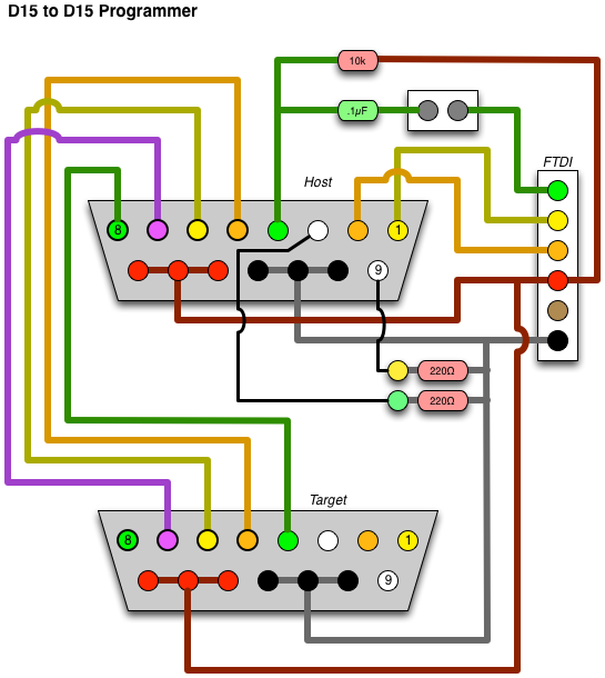
The full circuit diagram for the D15-hosted programmer, connected to a D15 target.
(The wire colors are the same as the above for reference.)

Once this is all wired up, we can get some firmware down onto that thing.  In our case, we have a device that isn't directly supported by the Arduino IDE, so we need to configure that first.

Two things need to be installed. First is the board definition, second is the optiboot hex file. Both of these content files can be grabbed from my Geodesic Sphere repository.  Full instructions are also there as for specific directories on Windows and Mac for doing this installation. The "readme" there shows the text block to drop into your "Boards.txt" file, and where to find that file.  You will also need to drop the optiboot.hex file into the "optiboot" folder as well.  Once these two steps are done, you can start up the Arduino IDE and you're ready to program.  Let's also assume that we've already externally kickstarted this, and the "Arduino ISP" sketch is already on the host device, and is running properly.

Here's where it gets confusing.  What? You're not already confused?  HERE WE GO!

Fire up the Arduino IDE, and let's set it for the D15 device.  From the "Tools" menu, select "Serial Port" and select your FTDI interface's serial port name.  Next, from the "Tools" menu, select "ATmega168 at 7372800Hz (D15)" from the "Board" menu.  This will tell the IDE what our target device is.  Now, from the "Tools" menu, select "Arduino as ISP" from the "Programmer" menu. This is all one-time configuration stuff.  Now, you can plug in a target D15 widget to the end of the cable seen above, and then select "Burn Bootloader" from the "Tools" menu.  A bunch of lights should flash, and you'll end up with the Arduino bootloader on the target widget!

On the above setup, it's wired such that you can also use it to test the target.  Disconnect the FTDI cable, disconnect the ICSP widget, and move the newly programmed device into the DB15 connector on the board.  Adjust the jumper so that "RESET" is enabled.  Now plug the DB15 cable back in.  This is now the equivalent to using the DB15 as a barebones Arduino.  Load up the D15_Test sketch included in the github repository mentioned above.  Click the "upload" arrow button, wait a moment, and the LED on the target widget should be blinking.  That's it!

One alternate way you can use this is to program your Arduino code onto the target widget without installing the bootloader.  These widgets use an ATMega 168, which has very constrained space, so this might be preferred for larger programs.

Hook it back up in the programmer configuration, with the ICSP widget on the board, the target on the cable, and the jumper set to disable RESET.

From the Arduino IDE, instead of just clicking the "upload" arrow button, hold down the [SHIFT] key, and the text will change from "upload" to "upload using programmer".  It may take a moment longer, but the end result is that you will see the LED blinking on the target widget.

You can use this to program other Arduino-like devices too (ATMega, ATTiny, etc).  You will just need to breakout the 6 lines (MOSI, MISO, CLOCK, RESET, +5v, GROUND) to whatever pin header configuration or socket is necessary.  Then you can just select the target device from the menu as appropriate (ATmega 168, 328, 5v, 3.3v, etc) and then select "Burn Bootloader" from the menus as above, and it will put the appropriate serial bootloader onto the device for you.

Thursday, January 24, 2013

Tron Arcade Monitor Repair


I won't lie to you.  Having an arcade machine is a lot of fun.  I used to have about 6 of them, but I'm down to two, due to space restrictions and general sanity.  The two that I still have are a TRON Mini/Cabaret, and a generic full-size cabinet into which I can put one of a few game motherboards that I have. (Dig Dug, Mortal Kombat, Klax, Rampart, and a few others.)  But one of the less glamorous sides of collecting machines is troubleshooting and repairing these 30 year old beasts.

I bought the Tron Mini in the late 90s as an empty cabinet.  I was having a difficult time back then finding an affordable Tron board/control set to install, so I instead put Satan's Hollow into it.

Tron Cabaret cabinet with Satan's Hollow - Note the red joystick and white "shield" button instead of the standard blue stick and spinner from Tron.

Over time, I found all of the parts needed including a few tricks to restore this.  When I put the Satan's Hollow boardset in, I rewired/hacked/brutalized the wiring in the cabinet to accommodate SH.  Although SH used the same boardset, the controls were wired differently.  Once I got the Tron board, and realized how rare this machine really is, I re-wired it using a wire harness from a junked Tron machine.  I also found the correct power supply to install, repaired by a fellow collector.  The controls were also out of another junked machine.  Over time, I got the machine as restored as I could get it. 

Tron uses a boardset, three boards connected together, from Bally/Midway called "MCR-2".  It consists of a CPU/Program board, a Video/Graphics board, and a Sound/IO board.  Midway used this boardset for a few games, including Tron, Satan's Hollow, Two Tigers, and a couple other ones.  If you have a ROM programmer (which I do), you can buy one of the cheaper boardsets to use as a replacement for one of the more desirable machines.  Tron boardsets, when I was last looking, sold for about $75-$150.  Two Tigers sold for about $40.  The boardset I have Tron running on right now is a Two Tigers boardset.

When restoring a game, there's a line to walk with respect to what parts to put into it.  This machine has some vinyl veneer on the sides, which are somewhat damaged.  It also has a fair bit of wear on the front edge of the control panel.  I could have tracked down a replacement/reproduction for these parts, but I'd rather keep it factory original.  It's not like the damage is too severe for either issue.  I'm actually very happy with the overall condition....  except for the monitor.

The cabaret/mini cabinet uses a 13" monitor, compared with the full-size's 19" monitor.  The monitor on this one showed a wavy haze, distorting the image a little, and mucking with the brightness across the screen, which you can kinda see here:


I was given a solution about 11 years ago, involving modifying one of the boards in the monitor (the "neck board", which connects directly to the back of the picture tube) but never did it, and lost the parts a few years ago.  I instead bought a "cap kit" from Amusements Plus around 3 years ago, and decided to install it.  The last time I did one of these was in 2001, so it's been some time.  

Love that desoldering iron!  The pump just clears out all of the solder super fast!

All of the caps in the cap kit have been replaced.  Shiny new caps on the board.  Old, dusty, puffy caps in the plastic bag.  I'm not entirely sure why I kept them...

Thanks to the awesome desoldering tool at Interlock, I was able to do this in about 45 minutes, rather than the 3 hours it took me years ago.

The board is mounted into the monitor framework, and reconnected to the picture tube.


Just about all of these knobs needed to be tweaked to get the picture looking its best!

After some calibration of adjusting all of the controls (focus and drive on the flyback transformer, and R/G/B Drive and Cutoffs on the neck board), the picture looked better than it has ever looked before! Which you can't really tell from these pictures, but trust me, the picture is sharp, colors bright, and the imagery is stable. It's like it's a new monitor!

The boardset I had in it at first was the Satan's Hollow with my ROM hack so that it will work as a drop-in for TRON arcade cabinets with no rewiring at all.


Yeah, a horrible high score, but just let me practice and remember my old strategies!

The above pictures were taken before I realized how much dust had accumulated on the picture tube and shroud.  I've since removed the artwork glass as well as the tinted plexi below that, and cleaned off those items as well as the picture tube itself.  That eliminated all of the haze, and improved the picture as well!

Hopefully, I'll get 30 more years of life out of if!

Soon, I need to mount a bunch of UV LEDs in the cabinet to illuminate all of the art work.  That's one of the features of the full-size cabinet that I really miss.

Thursday, December 13, 2012

Smörgåsbord 1

Some nights when I head to Interlock, rather than having one single project, or a part of a larger project to work on, I have a bunch of little things I want to get done.  They have the tools and materials I often need to do this.  This past Tuesday was one such night.  I had four things I wanted to work on, and I got all four done!

1: I like to put handles on things.  My favorite handles are from Lowes or Home Depot, and are called "wire drawer pulls" as seen in the image above.  They're relatively inexpensive at about $2, and are simple to install.  Generally they would be put on drawers in a modern kitchen or a clinical-type setting, but I like to put them on everything.  If something is portable, it should have a handle.  I just drilled two small holes in the plastic parts bin seen above, shoved the screws in from behind with some washers, and done!  I've used these handles for portable drive carriers, and other now-more-portable things.

2: Jasper sometimes breaks his toys.  I usually am the one who fixes them.  Above are two wood bolts from his workbench.  The threaded screws came out of the bolt heads.  I just scraped out the glue from the holes, and cleaned up both sides with a rasp and some other things that probably weren't designed for such things.  I added some wood glue, threw them in these clamps, and returned the screws to Jasper in the morning.


3: I had tried to fix my DLP projector a few weeks back.  There was something in the light path making half of the image dim such that if you shook the projector, it would clear up a little. I tore it down, and right between the spinny color wheel and the mirrors in front of the DLP chip is this little mirror tube collimator. The glue holding the four front-surface mirrors to the rectangular metal box had failed, and the mirrors became loose.  A couple weeks back, I had tried gluing it back together with epoxy, and it seemed to work, but a new, harsher shadow was in the projected image.  I needed to get some dental tools, mainly the little mirror tool, to see what was going on.  Sure enough, this little guy was aligned incorrectly.  A bunch of futzing with it later, and it is now fully functional!  


4: I have been building little breakout boards for my stepper motor controller-turned-arduino boards.  I decided that for the animatronic bird project, I wanted to have a way to input joystick data.  I made a small adapter to go from PC Gameport Joystick to the widget.  I followed this project here for the correct circuit -- basically just some pullups on the digital button inputs, and some pulldowns for the analog axis inputs.  I only wired up the first X/Y pair as the widgets only have two analog inputs available.  It was relatively simple to build.  I had built the main breakout board the night before at home, and i made the orange-wire to Gameport connector cable at Interlock.  With help from Nick, providing the old joystick, before I left i had written an auto-scaling display of the current joystick state.  More about this to come in future posts.

All in all, it was a densely packed evening, with four mini-projects completed.  Huzzah!