
I often check the recycle pile on the loading dock at work. I sometimes find smallish hard drives, old laptops, and various other bits and bobs that I might use for various projects. Often, most of them are useless, broken, beyond any sort of repair, but occasionally, I find something that is really useful to me, or I see the potential in something I find there.

One day, I went back there and found a few boxes of stepper motors attached to motor controller widgets. There were a few different models of these widgets, but they all seemed similar. They have a standard D-15 connector on one end and a 4 pin Molex pin connector on the other side. When the guy who put them out there saw that I had grabbed a lot of them, his only comment was "You don't want those... they're (explative deleted)!" I was about to prove him wrong.
The little stepper motor controller widgets intrigued me. I figured that I could use them to drive the motors or do something interesting along those lines. Turns out that the motors themselves are in fact... garbage, but the controllers would show to be very useful. I got access to some code that would talk to them, along with a few of the original wiring adpaters as seen above, with a D9 for serial RS232 control, and a two pin molex for power. I figured I could hook up power and drive them directly.

There are two different versions of the D15 widgets. One has a metalized plastic shell, the other has a metal shield wrapped around it and appears to have been potted with epoxy or hot glue. I cracked open one of the plastic shelled ones, and was checking out the innards. I figured i had a lot of them, might as well see what was in there. Both of these different styles have the same inner board.

As you can see, there is a power regulator (8 pin package), power transistors for the stepper motor coils, an LED, a 7.37 MHz crystal and a micro. The micro is an ATMega 168. This is the same chip used in the older Arduino boards, albiet at 7.37MHz instead of 8, 16, or 20 MHz. If I could figure out a way to get the Arduino bootloader onto one, or just make a programmer interface for one, then I could use them all as Arduino-compatible micros.
At this point, the possibilities of use for these things became apparent. I went back to the loading dock recycle pile and snagged the rest of the widgets, leaving the (mostly broken) stepper motors there to be recycled.

I sat down and with very sharp eyes, traced out the wiring of the ATMega chip to the D15 header, the various components and everything. I also mapped out what the components on the widget are in Arduino parlance. In retrospect, I should have taken a photo or scanned the board and enlarged the image on my monitor. Live and learn.

As you can see, there's a few pins missing, such as most of the analog inputs (lower left) but there's a lot that's there. The important things to note are that the D15 carries all of the things important to reprogram these things, as well as to make them useful for other projects. Power, D0/D1 for serial, reset, a couple analog, and the programmer header pins D10-D13. I color coded the pins on the D15 connector side to match the wiring harnesses I made. L is the LED. 0,1,2,3 are the stepper motor outputs, and T is a test point header on the board.


The first thing that I made is pictured above. It's a D15 to FTDI header cable. This would let me find out a few important things. First of all, I can power it, and talk with it via Serial to see if i can even
do that much. Sure enough, I set the Arduino IDE's serial monitor to 57600 baud, and was seeing text have affect. If nothing else, I can use these as stepper motor controllers.
I had a few concerns about reprogramming these things. First of all, I wasn't sure if the chips have had their write protect fuses burned or not. This would prevent me from shoving any code of any kind onto them. The other major concern was that with the crystal at 7.37 MHz, it was an unknown if the Arduino bootloader would even operate correctly. It requires a RS232 connection to the host computer. If I were to use an 8mhz crystal on it, the baud rates would be outside of the RS232 tolerances and it wouldn't work. (It would be about 9% off.)
I decided that for this whole exercise, the best plan of attack was to do each step along the way with minimal effort, so in case I hit a dealbreaker snag, I could just walk away from the project without too much loss of effort.

The next step was to make the above cable. This let me program a D15 with minimal effort. The idea is that I would install the "ArduinoISP" software on a "host" Arduino, and just plug this, with a D15, directly into it.


There was a problem though. It was only able to successfully program about 1/4 of the widgets I tried. 3 out of 12 worked, the rest failed. Even at this rate, I'd still have 25 widgets I could use. I looked into the problem more, and it turned out that the issue was with the programmer itself.
The problem was that as the Arduino interface connected to the host Arduino, so that it can send the new firmware through it and down to the target widget, the act of it connecting to the programmer forced a reboot onto the host Arduino, shoving it into an awkward state, unable to react properly. After some scouring the net (the use of Arduinos as host programmers is fairly scarce.. It's mostly in forums in the form of "I can't get this to work" ... "nevermind. I got it to work.")
I came to the realization that I had to somehow prevent the host from resetting. There were two different versions of this that I've found. One is using a 120 ohm resistor to power, or a 10 uF capacitor to power. I deicded to combine the two, because why not, and came up with the right top portion of the following diagram:
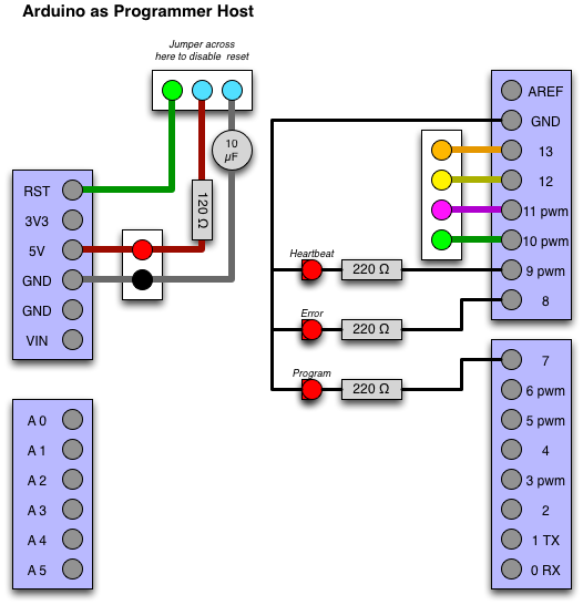
The right side of this also shows the indicator LEDs, which show what the programmer is doing. I figured I had to make a board for the reset circuit, I might as well add the indicator LEDs too. I unfortunately arranged the board poorly.

I later rearranged it to have space on the board for a ZIF socket to direclty program ATMega or ATTiny chips, which I'll show in a future post. (Yes, the layout bugged me to the point that I wanted to rearrange it.)
In any event, using this new circuit was easy. Plug the board in. remove the 3 pin jumper, dump the ArduinoISP project onto the host. Then shove the jumper back in place, plug in the target, select the target device type, and shift-click "upload", and I was able to get 100% success rate on every single widget I wanted to program.
The next issue was the crystal speed. I posted to the Arduino forums, asking how to rebuild the bootloader myself. Long story short (which you can read there), after some suggestions for replacing crystal and such, which I was about to do, Tom Carpenter responded with not only a compiled bootloader for this specific frequency, but with very detailed instructions about how to get it working. Thanks again, Tom!
I got this all set up on my system, downloaded the firmware to the widget, then plugged it in through the original FTDI cable I made earlier, and I was able to get the modified blink code above to work, while programming it through the standard Arduino interface without issues! I then extended the code to read and write serial to control the LED, just to prove that I was able to do everything on this.
I felt that the next important step was what I call "self hosting". This step replaces the host Arduino, the one that runs the ArduinoISP software, with another D15 widget. With the help of getting the definition of the board above, this was just as hard as making up a wiring harness. On this one, since I could disable the reset line by simply disconnecting it, I did this instead. On the FTDI interface board, there's a small white jumper that I can remove or install if I want to enable or disable the reset from the host computer.

This gets a little complicated to look at, but basically the top D15 connector is the host that runs the ArduinoISP software, and the bottom is the target device that will be getting programmed. If you notice D10-D13 are connected from the target (pins 4-7) directly up to 5-8. The reset line of the target is connected to D10 on the programmer, so that it can reset the target.

In execution, it's a little easier to understand. The above shows the FTDI board connected to a USB cable on the left, and the interface board with its white jumper in the top center. Next is the host device in the bottom right, which contains the programmer software. Then the center-left connector is where the target plugs in.
I was concerned about the timing being slightly slow (9% as mentioned above) affecting programming of the target devices, but it turned out to not be an issue. Like the above one, using a shield and a real Arduino, this is also 100% reliable as far as reprogramming target devices.

At this point, it's basically done. I've fully documented the widgets, I'm able to reliably program them... Next up was to show off a bit. The first thing I did was the above. I wrote a simple Arduino sketch that rotates the stepper 360 degrees, then rotates it the other direction a random amount, blinking the LED. I set this on my desk at work with a Tron Light Cycle, using a stepper that mostly worked, just as a slap in the face to them saying "look... these things are actually usable!"

I decided I wanted to play with charlieplexing some LEDs, (article to come in the future), so I made the above interface board (which I could also plug into a standard Arduino for debugging it). I plugged this one in to a 9V battery, and left it on my desk. On the display I had it flashing the text "(company name) RULES! !"
All of this happened a couple hours here and there, a few hours at the workbench at home, a few hours at the workbench at Interlock. Probably 20 hours total, stretched out over a couple of weeks, with the end result that I now have a huge amount of Arduino-programmer-compatible microcontrollers for free!
Soon, I'll tell you about a project to use these things; using dental floss containers as project boxes!

NOTE: There is an addendum to the circuits in this post over here.
Very cool dumpster find, and very cool of you to post about it.
ReplyDeleteLookingforward to your next post on the mystery project!
That is a lot of flossing you have to do :))
ReplyDeleteso nice ...^^
ReplyDeletelololololol... !!! I recognize those! I built those years ago, in Boulder. It was one of my first engineering jobs when I was a student at CU. Hahahahaha... Say hi to Vern for me!
ReplyDeleteOh, BTW, if you haven't reprogramed all the motor controllers, try this: just use a terminal program (RealTerm, Tera Term, whatever) to communicate with the controllers. You've already identified TX and RX. Set the baud rate to 57600.
Here's the product (or a really similar one) on the company's website:
http://www.excitron.com/webdocs/Items/Details363.cfm
And here's the manual for using the motor controller via a terminal interface:
http://www.excitron.com/webdocs/pdfs/Controller_Manual.pdf
Those controllers you have are pretty old, so not everything in the manual is relevant. Enjoy your Vern-junk!
So you got all of them to work in the end?
ReplyDeleteYep. Every one i've tried to reprogram has worked so far! :D
ReplyDelete