Wednesday, November 13, 2013

Cheap contiuity tester


I am working on restoring/repairing a Macintosh SE/30 machine, and I'm at the point now where I'm debugging why SCSI isn't working on it anymore. I found some schematics for it online, as well as some troubleshooting guides.  The project ahead of me was to 'buzz out' all 44 pins of the SCSI interface chip to points elsewhere on the board, to figure out why it's failing.  I knew I'd need a good continuity tester for this.  I have this feature in my multimeter, but I didn't want to hear that annoying beeper... I wanted a visual response instead.

I had toyed with the idea of using an LED Glow Stick flashlight, like I used for my "Sonic Screwdriver", just add in two wires going to test points.  I swung by the auto parts store, and instead saw this there for $10:

I decided this was a good starting point.  The light up portion was originally made for an incandescent screw-in type light bulb, but has been replaced by an LED, which doesn't work awesomely at glowing that end, and the alligator clip should be something a lot more precise, so those are the two things I decided to address.

First thing that had to go was the alligator clip end.  This is going to be touching into very fine-pitched electronics, so I needed something more precise.


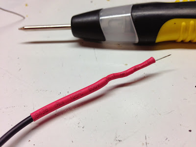
I snipped off the clip, and soldered the wire to a plain old straight pin, and then snipped off the pinhead. To make a handle of sorts, and to shield the exposed wire, I just used some heatshrink tubing.  I intentionally used too much heat shrink to stiffen the end of the wire and give me a place to grip it.

The LED in it was a bit... lacking... So I added in a bit of reflection using some metal foil tape, to try to let it glow better when it's on too.

The end result is pretty simple, but very useful.  That pin can really get onto any of the densely packed pins I need to test, and pierce through any oxide or muck on the joint.

Knowing now how easy it was to make the "probe" here, and how well it works, I think I might go back to my original idea of using an LED Glow Stick flashlight, and just tapping into the circuit to add in two probe wires, terminating in these pin probes.  In retrospect, I already had everything I needed before I bought this thing. Heh!

Thursday, October 17, 2013

Visualizing ROMs 1: Diode Matrix ROM


As a part of my BarCamp Fall 2013 presentation about visualizing ROMs, I decided to build a Diode Matrix ROM at Interlock this week. I should note that this is not practical, but it was a fun exercise in making physical data.

To start with, ROMs come in a few different varieties.

The most well known are EPROMs.  These are ICs with a quartz window on the top, through which you can see the storage array on the silicon.  This window is used to erase the ROM with ultraviolet(UV) light, then you can use a programmer to re-burn the ROM with other data.  It remains mostly non-volatile, unless it's erased with UV light again, via an eraser or by leaving it in the sun for a couple weeks.  These kinds of ROMs are useful for when you need to reprogram the content, or if the production runs are relatively small. These are often used in video arcade machines, as the program or graphical data might need revisions, and production runs are not in the "millions".

Another kind of ROM is the PROM, which is progammable once. It does not have a window on the top, and cannot be re-erased, as the bits are stored by actually burning out links on the IC.

Yet another kind of ROM is the Masked Rom. (Not related to Zorro or Mask Man.) This is not programmable at all, as its data is formed in the IC fabrication process.  Many mass-produced devices use this, like BIOS ROMs for PCs, Kernel ROMs for the Commodore 64, Kickstart ROMs on Amigas and so on.

Another way to produce a ROM is to actually physically build one using diodes at each of the bit positions. This makes for physically large ROMs, but is useful for very small production runs of very small amounts of data. In the past, Diode ROMs were used for boot programs for early mainframes like the DEC PDP-11, and are currently used for model railroading electrical logic.  I decided to make one of these.

Documentation on how to build one is a bit sparse, as not many people have bothered to make one, for obvious reasons. I went forward anyway and "winged it".  I built what you see in this in one evening at Interlock. I will attempt to describe the basic theory of operation in this post.


The data in a ROM is generated when an address is fed into the chip, and an enable line is activated.  This goes into the ROM chip, and activates the data bits at that address.  Those bits are then reflected out to the data output of the ROM itself.


For my example, we will make a 24 pin "part" that simulates use of a 2716 ROM, using its pinout.  We will plug this into my EPROM reader/programmer to dump out the contents.  More on this later...  Due to the nature of this circuit, I will be ignoring all of the address bits above A1, the activate/latch functionality (OE) as well as the programmability of a standard EPROM.

We will only look at address bits A0 and A1.  This means that there are four possible addresses we can use. A0 and A1 from the chip socket are wired into a "demultiplexer" chip, 74LS139. When A0 and A1 are (0,0) the '139 will enable only Output 0.  When they are (0,1) it will enable only Output 1, and so on.  Since the upper bits are ignored, once this reaches past (1,1), and becomes (1,0,0), we will read it as (0,0) and we will produce the same outputs. This means that our content will repeat over and over again, since I ignore bits A2-A10 of the address lines.

In the diagram above, the upper chip pinout sketched is the '139.  the two inputs are on pins 2 and 3, and the outputs are on pins 4,5,6,7.  The lower diagram shows the 2716 part pinout.  A0 and A1 from pins 7 and 8 go to the '139. Data output from our diode matrix goes to pins 9-11,12-17, to be read by the EPROM reader.


The above is shown in this diagram as the top two chips.  The diode matrix is shown below.  The orange lines are the outputs from the '139 part, as AD0, AD1, AD2, and AD3.  It will output 0v (active low) on only the selected line, and +v for the three other outputs.  Our diode matrix has 8 data bits shown as D7..D0 above.  Those are weakly pulled up to +v.  At the junction of any of the address lines (orange), and any data line (black), a diode can be added to signify a digital "0" as the diode will pull the current from the pullup'ed data line down to 0v.  If no diode is present, it will remain pulled up, tp +v, or a digital "1".  I should note that the values for each of the data pins are 0x80 (1000 0000) for D7, 0x40 (0100 000) for D6 and so on down to to 0x01 (0000 0001) for D0.

We want to output "Hi! ", repeating in the rom, so the four bytes we need to store are the ascii values for these characters, 0x48, 0x69, 0x21, 0x20... in binary form, this is (0100 1000), (0110 1001), (1101 0001), and (0010 0000).  As you can see above, if you look at the first of these, and read across you will see the presence of a diode where a '0' is signified, and lack of a diode where a '1' is.


The above image shows the physical interpretation of this circuit, annotated.  The 2716 connector is in the top right, '139 demultiplexer just below it on the right.  Its outputs become horizontal traces on the back (see the below image) to which the diode cathodes are connected, and the data bits become vertical wires on the front, to which the diode anodes are connected.  The pullups are at the top, connected to a +5v bus at the top. (Note: after this photo was taken, the blue data lines at the top were crazy-glued down to tidy them up a bit.)

The back of the board (kinda) shows the horizontal traces.  Trust me... it's there.  Stripboard isn't always easy to understand by looking at it. ;)


Since the Needhams EMP-10 requires a parallel port, and a MS-DOS based software package, I have dedicated my old Toshiba Libretto 50 only for running it.  It has Windows 95, a 10 gig disk, and not much else.  You can see it running scandisk as it boots Windows 95. Fun.  I could buy a new programmer, but why bother when this works well, and a new programmer is expensive.


So I built this board, and put it into my Needhams EMP-10, and I can retrieve the content out of it.  The notch on the right is so that I can use the latching lever in the ZIF socket.


And here you can see the buffer read in by the programmer.  The physical rows of diodes have become non-physical data inside of the computer. It's sorta like the digitizer in TRON, but not really. ;)

Bonus picture...

The following picture shows when it was not working correctly, before it was debugged.  There are a few things wrong, starting with some accidental shorts on the back tying some data lines together (not shown), but there's also one major issue here, and a bunch of minor issues here which are visible in the following photo.  See if you notice them...


Do you see the mistakes?

To start with, the 3rd data line from the left (D5 or 0x20) is both running to the wrong side of the diode, and is also not soldered to it.  The mistake harder to see is that the top two horizontal rows of diodes are completely not soldered to the data lines at all.  If they outputted anything it was accidental.  This is what happens when you're tired and too quick to plug it in and try it out without visually inspecting it.  Oops!

Update:  This article was featured in Hack A Day on October 18th, 2013.  Hello friends!

Friday, August 16, 2013

My all-in-one Pi


I have a Raspberry Pi, but I wasn't sure how to encase it or whatever.  I picked up a bunch of these 13" LCD monitors from the scrap heap at work.  They run on 12v, and have VGA, S-Video, Component and Composite inputs.  I figured that I wanted to use one as a display for the Pi, so I started with trying to suck 5v of power off of the mainboard inside of it.  After a little probing with a multimeter, I found a 5v and Ground that seemed like a good place to tap.


I sacrificed a micro usb cable to tap directly onto the motherboard.  On the left you can see where I zip-tied it to the frame to prevent strain on the soldered connection.


The cord comes out from an unused port opening.  I added the two screw/standoffs you see on the bottom right.  I should note that I also removed the fan whose grille you can see in the top of the frame.  The fan wasn't needed, and was super noisy.  Next thing to do is to mount the pi on the back of the case.


Huzzah.  Everything fits nicely.  A short composite cable to hook it up and it's ready for use... Only problem was a way to prop it up.  I was going to build some sort of stand for it, but after looking around the parts area of Interlock, I found a broken Dell monitor I had brought in months ago.  I decided to repurpose its stand.


I removed the plastic backing from the upper portion, then removed the mounting plate from the stand.  I added four more holes to line up with the four screws coming out of the monitor (which have a ball joint as seen above) and use those to mount it to the stand.


After assembling it all together, it seems to work nicely.  I've since zip-tied the power brick to the back as well, although I'm not sure I like the way that works out.  The USB and ethernet ports are underneath the stand.  I'm considering moving the pi to be on the back, along the right side rather than on the back along the bottom.

You can also see in the above picture that I have added in a handle on the side of the monitor as well.  It's just the same kind of wire/metal drawer pull as I've used in the past.  It adds a nice carry handle to the project.


All of the ports of the Pi are still easily accessible.

Wednesday, July 10, 2013

BL-328 Computer: The keyboard

I was going to integrate this into the megapost for BL328, but there was enough here that I wanted to give it its own post.

For a while, I was thinking that I wanted to use a PS2 keyboard for my BL-328 computer.  This would have worked well; being just software serial to receive PS2 messages from the keyboard, and sending down RS232 keys, or just integrating it right into the main board of the device, using the above.  Space was getting tight on the main board, but I could have made it work.

One fateful trip up to Active Surplus up on Queen Street in Toronto, Canada changed that idea.  (NOTE: this is one of the reasons I love browsing there.  I wish they were closer!)


I found this.  It's a Commodore 16 keyboard.  I remember looking up Commodore 64 keyboards at one point, and they were a simple matrix.

Keyboard matrices work pretty simply. You have a grid of wires in the horizontal and vertical.  At each intersection, there's a switch (one key on the keyboard).  To "read" it, you send out a signal on each of the horizontal lines, then read in through each of the vertical lines. If you see the signal on the vertical line, you know that the intersection of that vertical with the horizontal that you sent out the signal on is where there's a key that's pressed down.


I made an interface for this using an old serial Arduino board, a Seeed Studio shield kit, and a bunch of wire. Above you can see the early version of this before I had everything figured out.  The above worked somewhat, but had to be directly plugged in to an Arduino.  I've since added a FTDI header for communications, as well as switching around one line to he header.  On the Arduino boards (and on this board) Digital 13 was broken out to an LED for display.  This interfered with the keyboard scanning, so I had to rewire it a bit.  The topmost red line was swapped down to be just below the bottommost line.  It made the code a little confusing, but it all worked out.

In a testing configuration, directly wired in to an Arduino Pro.  Notice that I'm using a Commodore 64 keyboard instead of the Commodore 16 keyboard purchased/shown earlier.

Detail showing that one rewired line on the controller board.  This is also after I mounted the Arduino, Shield and keyboard on a piece of lexan.  Rubber feet on the bottom, underneath the keyboard keep it nice and sturdy.  This also shows the three-wire serial at the top of the image, which connects it to the host computer.

Hooked up to a test display to get a feel for how it would work.
And as a part of the completed system.  CPU board is in the red project box, with a battery pack sticking out from it.  Keyboard and controller sit on the bottom of the image.  Between the two is the video display module, sitting on its plexiglass monitor stand. I also settled upon a color scheme for the keyboard as well.


Wednesday, June 26, 2013

Tiny FTDI adapter for the D15 Stepper Motor Controllers


Here's a quick one. I wanted a VERY compact FTDI interface for the D15 devices, that didn't offer any IO pin access, just so that I could try building stuff to the Atmega 168 in there, and chat with it through serial.


Rather than using the cable I made and showed in previous posts, I decided to just do point-to-point soldering of a 6 pin header directly to a D15 connector.


The results are that I have a very compact device to play with.  It's very portable too!

Tuesday, June 25, 2013

Microphone Mount for my Voice Recorder

I like to audio record stuff, and have since I was a kid.  I recently got a Sony ICD-PX820, which records to MP3 files, accessible through USB, which is super handy.  It has a proprietary database file that contains the time and date of the recordings, and probably some other information. I somewhat recently reverse engineered this file enough to retrieve some information out of it, and made this available through github.

One of my minor issues with it, is that although it does record decently through the builtin microphone, it's mono and of limited dynamic abilities.  I found that I could get decent recordings by using the stereo mic I bought many moons ago for use with my DV camcorder.  The Sony has a mic jack on it, which is perfect, but it only has two gain settings "High" and "Low".  It's enough to get by, until I buy a real portable recorder.


The one problem I had with this setup though is that there was no way to easily carry it.  I decided to make some sort of mounting adapter to attach the microphone to the voice recorder.  The mic came with a clip with a hotshoe/tripod mount on it, as well as a little extension arm which also has the same abilities.   I decided that the best way to take advantage of this was to mount a screw through the case of the voice recorder, and attach the mic to this.


I started by mapping out the best locations for screws. I decided to make two holes, so that I would be able to switch it around if I needed to.  The screws I have, have heads that are a little too rounded, so they force the battery cover up a little bit, but it's good enough for now.


In the future, I'd like to try flatter-headed screws for this design.  I'd also like to perhaps try a 3D-printed thing, which the voice recorder can be snapped into, and the microphone slid into the bottom, to make it more sleek.

Friday, May 17, 2013

11 Digit, 7 Segment Display

An early test result, showing text and millseconds since power-on.

About a year ago, I bought a few 11 digit, 7 segment red LED displays from Active Surplus up on Queen Street in Toronto. (Excellent store.  If you're into hacking stuff at all, it's well worth the trip. Look for the monkey on Queen street to find their entrance.)

This past week, I wasn't sure what to do at Interlock on Tuesday night, but I had recently re-found these displays, so I figured I would finally get them working.  I hit Radio Shack to get a Seeed Studio Arduino Shield ($10 with a mess of components, probably the best deal in all of Radio Shack.)

The display with a header soldered on, and the shield with its assorted parts.

I was all set to figure out how to reverse-engineer the pinout on the bottom of the display; I googled for the LED module, and found specs on those, and then on a whim, decided to check on the entire module board, a Rohm LU-3011, and found the jackpot, this post about figuring out the pinout.  It suddenly became very easy to do this project.

The two key things gleaned from that above post, which I have mirrored here, are this table of enables for each of the 11 digits:

Digit1234567891011
Pin1234681012141618

and this image, showing the pin mappings of the segments:
Mapping of the segments to the pins on the header.

The basic way these displays work is that all of the 7 segments (plus one decimal point) are all tied together to the pins specified above.  Then the anodes for each of the displays are broken out to the pins in the table above.  So to draw a '7', you would set all of the segments to LOW, except for pins 11, 19, and 7 which you set HIGH.  Then to turn on a specific digit, let's say digit 11 (rightmost), you set the digit enable pin 18 to be an output, and set it LOW.  Set all of the other digit enables to be inputs (tri-state, not low or high), and only position 11 will show a "7".  You repeat this for all of the 11 digits in the display, and you can display 11 full digits from just those 19 pins. 

In my code (available below) I start at digit 1, and work down to digit 11, enabling each one, in turn, showing its segments, waiting 1 millisecond, then disable that digit, move on to the next one.  Because of this quick display time, and to preserve brightness, I did not put any current limiting resistors in the mix.  Perhaps this was a bad idea, but it works great for now. ;)

I soldered a pin header on the display, and built up a shield to plug it into.

All of the digit enables wired up.  The top ones are a bit messy. Sorry about that.

I wired it up such that the digit enables and segments are wired directly to IO lines on my Arduino.  This used all of the IO lines, minus the D13 pin, which has an on-board LED.

The code that I wrote (available below) lets you do arbitrary digits per character, so that i can do (primitive) alphanumerics, or do animation patterns, etc.  I also store the decimal point as a separate character going in to the display code, so "3.141" is five ascii characters going in, but a flag is set on the '3' position saying that this digit should also display its decimal point, so it only consumes four digits in the display.

just testing out all of the segments and digits

For now, it displays a nice clock and some animations on my desk, but I plan on changing it around a little in the near future.  I want to use the D13 line as one of the segment enables (probably decimal point) and move the segment enables off of the Serial Receive line.  That way i will be able to control it via serial to display patterns, animations or text content.  Since the hardware serial port is hardwired to 0 and 1, and I will be using the TX line for the LED displays, I'll have to instead use the Software Serial, with only its Receive line mapped to an IO pin, and its Transmit line mapped to junk. I've done this before and it works well.


This project was constructed and started at the Interlock Rochester hackerspace.

Monday, April 22, 2013

Barcamp Rochester Spring 2013 - Ridiculous use of Video Tech

On display at Barcamp Rochester this year was my Amiga-Genlock autotumblr setup.  It's a mix of technologies that span from 1985 to 2013.  It's fun, ridiculous and here's what's happening with it.  (Note: the complete list of technologies used is at the bottom of this post.)

Here's the basic workflow as it was planned:

And here's the slide I made to describe the system in Deluxe Paint 3, which is close to the same thing, but a little more (less?) informative: (Note: the color cycling is not available for this display, sadly.)

And here's a snapshot of it from the system itself, with some MST3K overlay goodness:


The Amiga 1000 is running Deluxe Paint 3.  You draw on a color 0-backed canvas.  The Amiga has an 8 meg ram expansion board attached to it via DataFlyer expansion module, and was running two floppy drives.

The Amiga 1300 genlock (which is hidden underneath the Amiga) replaces anything that is color 0 on the screen with the video input.  The video input in this case is connected to the old-school Minolta vidicon-tube video camera.  This gives us the Amiga graphics over top of the video coming in. I should note that all of this happens external to the computer itself, in the anlog video path.  The only thing going into the computer is the sync signal.  This means that if you were to "save" an image in Deluxe Paint, you will get only the mustache you drew, not it on your friend's face as well.

It's that overlayed image that we want here, so we feed that output video signal into the DV camcorder, which is acting like an AV-DV bridge in this case, only that we're ignoring the Firewire DV output from it.   Instead, we use a feature on this particular camera, in which it saves a screenshot of the current video to the SD card you have installed with it.

I should note that this camera came with an 8 meg SD card.  This should give you a sense of scale for the vintage of this thing.  I have instead replaced this with a 2 gig EyeFi card.  This EyeFi card is linked to my Macbook Pro via the wifi access point on the table.  The Eye-Fi software saves its content into a  Dropbox folder.  When a picture comes in, it then magically gets copied up into the cloud.

Once saved there, a script at IFTTT.com (If This Then That) takes the photo, and puts it into a tumblr post, which is then viewable by all in a standard way.


Here's a list of all of the hardware and technologies used to make this happen.
  • Amiga 1000 (Spring 1986 vintage)
    • AmigaDOS 1.3 (1988)
    • 7.16 MHz 68000 processor
    • 512k byte RAM (graphics, cpu ram)
    • Deluxe Paint III software (1983)
    • Commodore 1300 Genlock
    • Dataflyer 8 megabyte RAM expansion (1991)
    • Sony Trinitron 9" monitor
  • Minolta K-520 Tube Video camera (1985)
    • "VHS" connector, with custom power supply and AV interface connector
  • Canon Optura XI DV Camcorder (2003)
  • Eye-Fi Share (2007) 2 gig SD card
  • WiFi Access Point
  • Dropbox folder syncing software (current)
  • Linux Laptop running Ubuntu and Dropbox software (current)
  • IFTTT script to post new Dropbox items to Tumblr (current)
  • Images posted to http://amigapics.tumblr.com (current)
So... what happened?

In practice at home, this all worked well, both going through my home access point, as well as through the extra access point, connected to my laptop directly (whose wifi-based internet access was shared through the AP).  But once I got it all at RIT, that's where things started to break.

First of all, I forgot my Amiga floppy disks at home, so I had to run home to grab those.  Oops.

Next, there was a sync/color issue with the genlock when i got it all connected.  I'm pretty sure this is because of two things.  First, the Amiga doesn't sync with the genlock before the Kickstart disk is loaded... and without this disk on-hand, I couldn't fix this until I had gone home to get them.  Secondly, I think the RGB connector on the genlock is faulty, causing it to make a poor connection with the system.  I need to examine this more.

Next, the wireless network at RIT prevented me from re-sharing its network on my Mac.  It claimed some sort of 802.1x protection or somesuch. Next up was to get the Eyefi and macbook directly onto the RIT network. The Eyefi card I have (not sure if modern cards are like this) would not connecto to the RIT networks since the network required username/password, whereas the Eyefi software only supported a password for the network settings.  The Barcamp network dude helped me get both onto the unprotected RIT network (unlocked to the devices via MAC address, rather than user/password).  Unfortunately for some reason this didn't quite work with the card and laptop either.  I'm not entirely sure why.   I then had a friend with a linux laptop to share his wireless connection out through his wired ethernet, which then was re-shared via the access point I brought.  This kinda worked. but at rediculously slow bitrates to be useless.

It was pretty much at this point that I just gave up on the wireless aspect of the Eyefi card, and would just plug the SD card into my laptop occasionally and manually copy the files into the Dropbox folder.  Oh well.

Other than that, It worked pretty well.  All of the images captured are available on the tumblr site at least for now.

Here's some of them as well:

Brian and Skip at the Interlock table

Chorn talking with someone

Me, testing out the system

Dennis being frightened by a deadite.

Some Deluxe Paint fun


Just like old times, the Amiga crashed a few times.

Video feedback

Chris